Toyota FJ Cruiser (GSJ 10, 15 series). Instruction - part 180
1GR-FE ENGINE MECHANICAL – ENGINE UNIT
EM–151
EM
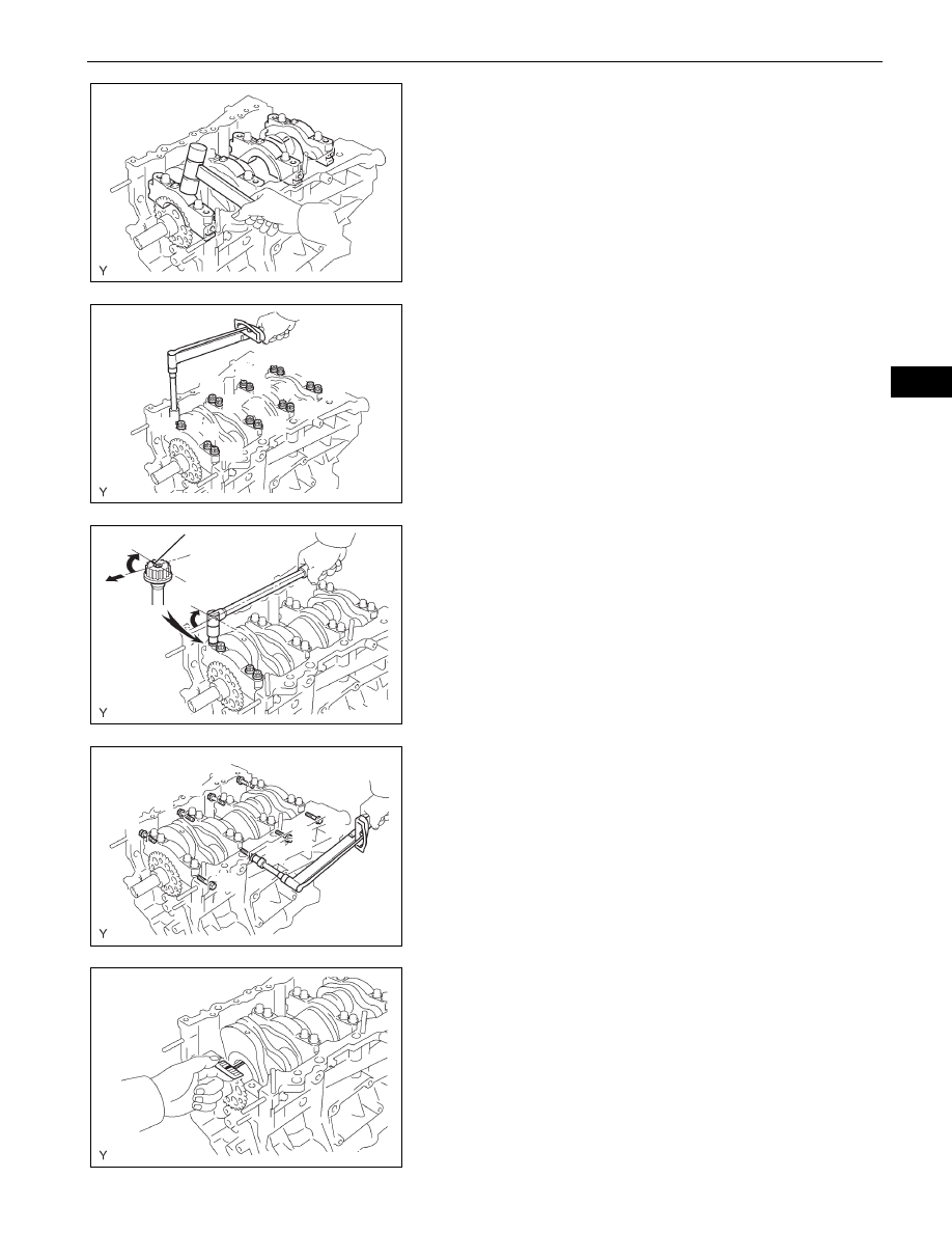
(i)
Using a plastic-faced hammer, lightly tap the
bearing cap to ensure a proper fit.
(j)
Apply a light coat of engine oil to the threads of main
bearing cap bolts.
(k) Install the 16 main bearing cap bolts. Using several
steps, tighten the bolts uniformly in the sequence
shown in the illustration.
Torque: 61 N*m (622 kgf*cm, 45 ft.*lbf)
(l)
Mark the front side of the bearing cap bolts with
paint.
(m) Retighten the bearing cap bolts 90
° in the sequence
as shown.
(n) Check that the painted mark is now at a 90
° angle
from the front.
NOTICE:
Do not turn the crankshaft.
(o) Install the 8 main bearing cap bolts. Using several
steps, tighten the bolts uniformly in the sequence
shown in the illustration.
Torque: 25 N*m (255 kgf*cm, 18 ft.*lbf)
(p) Remove the main bearing caps.
(q) Measure the Plastigage at its widest point.
Standard oil clearance:
0.018 to 0.030 mm (0.0007 to 0.0012 in.)
Maximum clearance:
0.046 mm (0.0018 in.)
If the oil clearance is greater than the maximum,
replace the bearings. If necessary, replace the
crankshaft.
NOTICE:
Completely remove the plastigage.
A076070E01
7
15
1 2
3 4
6
5
8
9
14
13
10
11
12
16
A076071E04
Painted Mark
Front
90°
90°
A076072E03
3
7
1
2
4
5
6
8
A075843E03
A075844E01