Toyota FJ Cruiser (GSJ 10, 15 series). Instruction - part 179
1GR-FE ENGINE MECHANICAL – ENGINE UNIT
EM–147
EM
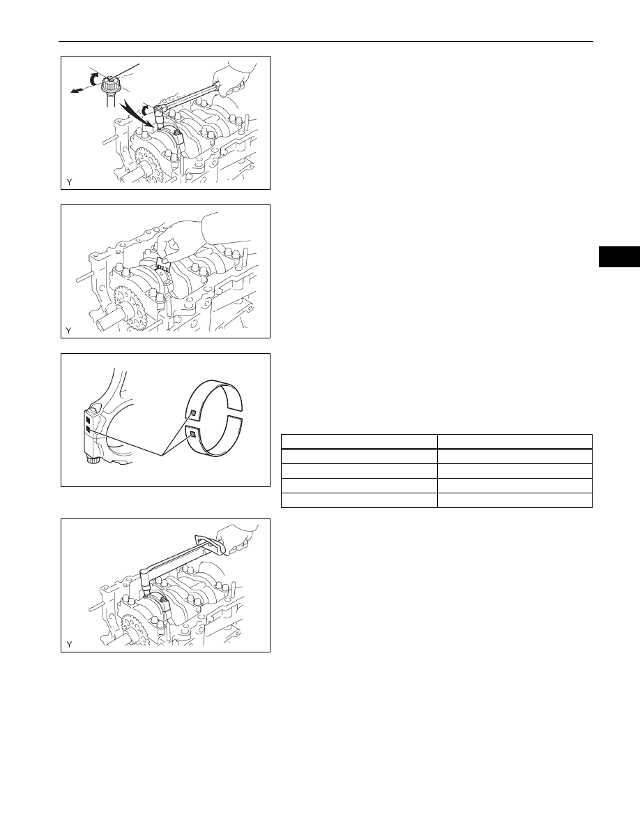
(i)
Mark the front side of the each connecting cap bolt
with paint.
(j)
Retighten the cap bolts 90
° as shown in the
illustration.
NOTICE:
Do not turn the crankshaft.
(k) Remove the 2 bolts, connecting rod cap and lower
bearing.
(l)
Measure the plastigage at its widest point.
Standard oil clearance:
0.026 to 0.046 mm (0.0010 to 0.0018 in.)
Maximum oil clearance:
0.066 mm (0.0025 in.)
NOTICE:
Completely remove the plastigage.
(m) When replacing the bearing, replace it with one with
the same number as marked on the connecting rod.
There are 4 sizes of standard bearings, marked "1",
"2", "3" and "4".
HINT:
Standard bearing center wall thickness
(n) Remove the 2 connecting rod cap bolts.
90°
90°
Front
Painted Mark
A075151E03
A075152E02
Number Mark
A126508E01
Mark
mm (in.)
"1"
1.484 to 1.487 (0.0584 to 0.0585)
"2"
1.487 to 1.490 (0.0585 to 0.0587)
"3"
1.490 to 1.493 (0.0587 to 0.0588)
"4"
1.493 to 1.496 (0.0588 to 0.0589)
A075150E01