Toyota FJ Cruiser (GSJ 10, 15 series). Instruction - part 178


  Index      Toyota     Toyota FJ Cruiser (model GSJ 10, 15 series) - service repair instruction 2007 year


Search            copyright infringement  


Content   ..  176  177  178  179   ..


Toyota FJ Cruiser (GSJ 10, 15 series). Instruction - part 178


1GR-FE ENGINE MECHANICAL  –  ENGINE UNIT

EM–143

EM

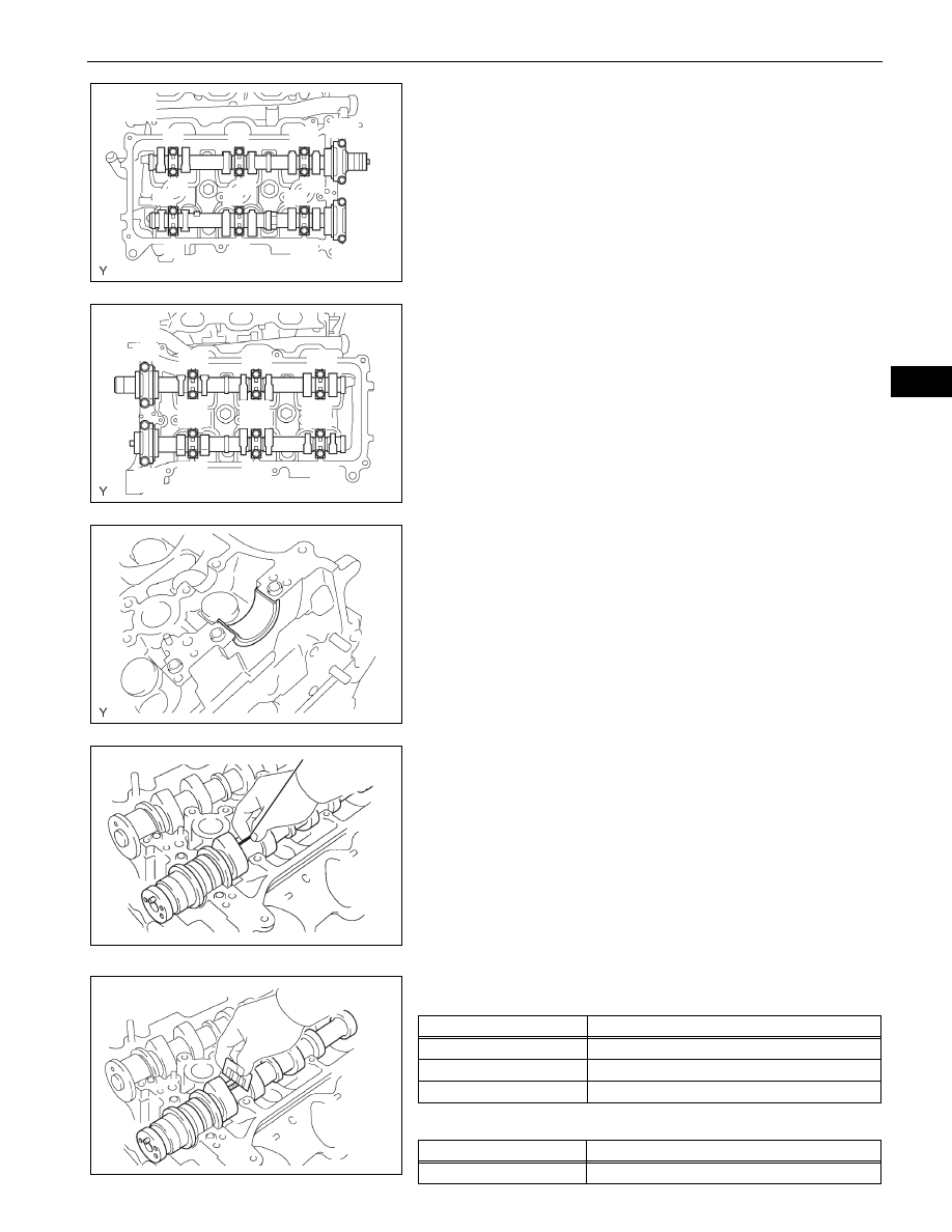
(2) Using several steps, uniformly loosen and 

remove the 16 bearing cap bolts in the 
sequence shown in the illustration.

(3) Remove the 8 bearing caps, then remove the 2 

camshafts.

(b) Remove the camshafts of bank 2.

(1) Using several steps, uniformly loosen and 

remove the 16 bearing cap bolts in the 
sequence shown in the illustration.

(2) Remove the 8 bearing caps, then remove the 2 

camshafts.

43. REMOVE NO. 1 CAMSHAFT BEARING

(a) Remove the No. 1 camshaft bearing from the No. 1 

camshaft bearing cap.

44. REMOVE NO. 2 CAMSHAFT BEARING

(a) Remove the No. 2 camshaft bearing from the 

cylinder head for bank 1.

45. INSPECT CAMSHAFT OIL CLEARANCE

(a) Clean the camshaft bearing caps, camshaft 

bearings and camshaft journals.

(b) Install the camshaft bearing.
(c) Place the camshaft on the cylinder head.
(d) Lay a strip of Plastigage across each camshaft 

journal.

(e) Install the camshaft bearing caps.

NOTICE:
Do not turn the camshafts.

(f)

Remove the camshaft bearing caps.

(g) Measure the Plastigage at its widest point.

Standard oil clearance (Bank 1)

Standard oil clearance (Bank 2)

1

2

3

4

6

7

8

5

9

10

11

12

14

15

13

16

Bank 1:

A072967E12

3

6

4

7

9

8

5

2

1

10

11

12

13

14

15

16

Bank 2:

A072968E11

A076279E01

Plastigage

A075622E02

A075623E01

Camshaft Bearing Cap

Specification

No. 1 (Intake)

0.008 to 0.038 mm (0.0003 to 0.0015 in.)

No. 1 (Exhaust)

0.040 to 0.079 mm (0.0016 to 0.0031 in.)

Others

0.025 to 0.062 mm (0.0010 to 0.0024 in.)

Camshaft Bearing Cap

Specification

No. 1

0.040 to 0.079 mm (0.0016 to 0.0031 in.)

EM–144

1GR-FE ENGINE MECHANICAL  –  ENGINE UNIT

EM

Maximum oil clearance (Bank 1)

Maximum oil clearance (Bank 2):

0.10 mm (0.0039 in.)

If the oil clearance is greater than the maximum, 
replace the camshaft bearings and/or camshafts.
If necessary, replace the camshaft bearing caps and 
cylinder head together.
Reference

(h) Remove the Plastigage completely.
(i)

Remove the camshafts.

(j)

Remove the camshaft bearing.

46. REMOVE CYLINDER HEADS

(a) Using several steps, loosen the 8 cylinder head 

bolts on each cylinder head with a 10 mm bi-
hexagon wrench in the sequence shown in the 
illustration. Remove the 16 cylinder head bolts, then 
remove the plate washers.
NOTICE:

Be careful not to drop the plate washers into 
the cylinder head.

Cylinder head warpage or cracking could 
result from removing the bolts in the wrong 
order.

Others

0.025 to 0.062 mm (0.0010 to 0.0024 in.)

Camshaft Bearing Cap

Specification

No. 1 (Intake)

0.07 mm (0.0028 in.)

Others

0.10 mm (0.0039 in.)

Cylinder head journal bore diameter

40.009 to 40.017 mm (1.5752 to 1.5755 
in.)

Camshaft bearing center wall thickness 
(Mark "2")

2.004 to 2.008 mm (0.0789 to 0.0791 
in.)

Camshaft journal diameter

35.971 to 35.985 mm (1.4165 to 1.4167 
in.)

Camshaft Bearing Cap

Specification

1

3

5

2

7

6

4

1

8

8

2

5

4

6

7

3

Bank 1:

Bank 2:

A072970E06

1GR-FE ENGINE MECHANICAL  –  ENGINE UNIT

EM–145

EM

(b) Lift the cylinder head from the dowels on the 

cylinder block, and place the 2 cylinder heads on 
wooden blocks on a bench.
NOTICE:
Be careful not to damage the contact surfaces of 
the cylinder head and cylinder block.
HINT:
If the cylinder head is difficult to remove, pry 
between the cylinder head and cylinder block with a 
screwdriver.

(c) Remove the bank 1 and bank 2 cylinder head 

gaskets.

47. REMOVE NO. 1 WATER OUTLET PIPE

(a) Separate the knock sensor wire.
(b) Remove the 3 bolts, then remove the water outlet 

pipe.

48. REMOVE KNOCK SENSOR

(a) Disconnect the 2 knock sensor connectors.
(b) Remove the 2 bolts, then remove the 2 knock 

sensors.

49. REMOVE REAR ENGINE OIL SEAL RETAINER

(a) Remove the 5 bolts and 2 nuts.
(b) Using a screwdriver, remove the oil seal retainer by 

prying between the oil seal retainer and crankshaft 
bearing cap.

A072971E01

G036807E01

A076270E01

Pry

A076247E02

EM–146

1GR-FE ENGINE MECHANICAL  –  ENGINE UNIT

EM

50. INSPECT CONNECTING ROD THRUST CLEARANCE

(a) Using a dial indicator, measure the thrust clearance 

while moving the connecting rod back and forth.
Standard thrust clearance:

0.15 to 0.30 mm (0.0059 to 0.0118 in.)

Maximum thrust clearance:

0.35 mm (0.0138 in.)

51. INSPECT CONNECTING ROD OIL CLEARANCE

(a) Check the matchmarks on the connecting rod and 

cap are aligned to ensure correct assembly.

(b) Remove the 2 connecting rod cap bolts.
(c) Clean the crank pin, bearing and connecting rod.
(d) Check the crank pin and bearing for any pits and 

scratches.

(e) Lay a strip of plastigage across the crank pin.

(f)

Check that the protrusion of the connecting rod cap 
is facing in the correct direction.

(g) Apply a light coat of engine oil to the threads of the 

connecting rod cap bolts.

(h) Tighten the bolts alternately to the specified torque.

Torque: 25 N*m (250 kgf*cm, 18 ft.*lbf)

A075147E01

A075150E01

Plastigage

A075148E02

Protrusion

A075149E02

A075150E01


Content   ..  176  177  178  179   ..