Toyota FJ Cruiser (GSJ 10, 15 series). Instruction - part 138


  Index      Toyota     Toyota FJ Cruiser (model GSJ 10, 15 series) - service repair instruction 2007 year


Search            copyright infringement  


Content   ..  136  137  138  139   ..


Toyota FJ Cruiser (GSJ 10, 15 series). Instruction - part 138


ENGINE HOOD / DOOR  –  BACK DOOR

ED–49

ED

9.

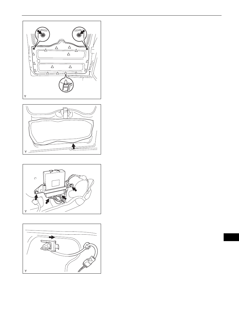
REMOVE BACK DOOR TRIM BOARD
(a) Remove the 2 screws.
(b) Disengage the 16 clips and remove the back door 

trim board.

10. REMOVE BACK DOOR SERVICE HOLE COVER

(a) Remove the back door service hole cover.

NOTICE:
Remove any tape remaining on the door side.

11. REMOVE REAR WIPER ARM AND BLADE 

ASSEMBLY (w/ Rear Wiper) (See page 

WW-39

)

12. REMOVE REAR WIPER MOTOR (w/ Rear Wiper) (See 

page 

WW-40

)

13. REMOVE REAR WIPER MOTOR GROMMET (w/ Rear 

Wiper)

14. REMOVE MULTIPLEX NETWORK DOOR ECU

(a) Disconnect the 2 connectors and harness clamp.
(b) Remove the 2 screws and the multiplex network 

door ECU.

15. REMOVE BACK WINDOW LOCK ASSEMBLY (See 

page 

WS-93

)

16. REMOVE BACK DOOR OUTSIDE GARNISH SUB-

ASSEMBLY (See page 

ET-90

)

17. REMOVE BACK DOOR LOCK ASSEMBLY (See page 

DL-116

)

18. REMOVE BACK DOOR LOCK CYLINDER ASSEMBLY

(a) Disconnect the connector and the 2 clamps.

B135554

B135544

B135545

B135546

ED–50

ENGINE HOOD / DOOR  –  BACK DOOR

ED

(b) Remove the retainer and the back door lock 

cylinder.

19. REMOVE NO. 1 REAR SPOILER COVER

(a) Remove the 4 screws and No. 1 rear spoiler cover.

20. REMOVE REAR SPOILER (See page 

ET-34

)

21. REMOVE HIGH MOUNTED STOP LIGHT ASSEMBLY 

(See page 

ET-35

)

22. REMOVE BACK DOOR SIDE FEMALE STOPPER 

SUB-ASSEMBLY
(a) Remove the 2 bolts and back door side female 

stopper.

23. REMOVE BACK WINDOW SUPPORT LH (See page 

ED-61

)

24. REMOVE BACK WINDOW SUPPORT RH

HINT:
Use the same procedure as described for the LH side.

25. REMOVE BACK DOOR GLASS (See page 

WS-63

)

26. REMOVE BACK WINDOW STAY UPPER BRACKET 

RH (See page 

WS-63

)

27. REMOVE BACK WINDOW STAY UPPER BRACKET 

LH
HINT:
Use the same procedure as described for the RH side.

28. REMOVE BACK WINDOW LOCK STRIKER 

ASSEMBLY (See page 

WS-63

)

29. REMOVE BACK DOOR OUTSIDE HANDLE (See page 

WS-64

)

B135548

B135550

B135549

ENGINE HOOD / DOOR  –  BACK DOOR

ED–51

ED

30. REMOVE BACK DOOR HINGE ASSEMBLY RH

(a) Remove the bolt and the back door hinge.

31. REMOVE BACK DOOR HINGE ASSEMBLY LH

HINT:
Use the same procedure as described for the RH side.

32. REMOVE NO. 2 BACK DOOR WEATHERSTRIP

(a) Remove the No. 2 back door weatherstrip.

NOTICE:
Remove any tape remaining on the door side.

33. REMOVE BACK DOOR STAY UPPER BRACKET RH

(a) Remove the bolt and the back door stay upper 

bracket.

34. REMOVE BACK DOOR STAY UPPER BRACKET LH

(a) Remove the bolt and the back door stay upper 

bracket.

35. REMOVE BACK DOOR SUPPORT (See page 

ED-59

)

36. REMOVE BACK DOOR DAMPER STAY LOWER 

BRACKET
(a) Remove the 2 bolts and the back door damper stay 

lower bracket.

37. REMOVE NO. 1 BACK DOOR NAME PLATE (See 

page 

ET-28

)

38. REMOVE NO. 2 BACK DOOR NAME PLATE (See 

page 

ET-28

)

39. REMOVE REAR NAME PLATE (See page 

ET-29

)

B135998

B135591

B135592

B135593

B135999

ED–52

ENGINE HOOD / DOOR  –  BACK DOOR

ED

40. REMOVE CUSHION

(a) Remove the 2 cushions.

41. REMOVE HOLE PLUG

(a) Remove the 2 hole plugs.

ADJUSTMENT

HINT:

Centering bolts are used to mount the door hinge onto the 
vehicle body and door. The door cannot be adjusted with 
the centering bolts on. Substitute standard bolts (with 
washers) for the centering bolts when making 
adjustments.

For bolts without torque specifications, check the standard 
bolt chart (see page 

SS-2

).

1.

INSPECT BACK DOOR
(a) Check that the clearance measurements are within 

the standard ranges.

Standard

Centering Bolt

Standard Bolt

B104980E01

Area

Measurement

Area

Measurement

A

8.5 to 11.5 mm 

(0.335 to 0.453 in.)

G

5 to 8 mm 

(0.197 to 0.315 in.)

B

0 to 3 mm 

(0 to 0.118 in.)

H

3.5 to 6.5 mm 

(0.138 to 0.256 in.)

C

5.5 to 8.5 mm 

(0.217 to 0.335 in.)

I

2.8 to 5.8 mm 

(0.110 to 0.228 in.)

D

5 to 8 mm 

(0.197 to 0.315 in.)

J

5.5 to 8.5 mm 

(0.217 to 0.335 in.)

A

B

C

D

E

F

G

H

I

J

K

B139380E01


Content   ..  136  137  138  139   ..