Toyota FJ Cruiser (GSJ 10, 15 series). Instruction - part 134


  Index      Toyota     Toyota FJ Cruiser (model GSJ 10, 15 series) - service repair instruction 2007 year


Search            copyright infringement  


Content   ..  132  133  134  135   ..


Toyota FJ Cruiser (GSJ 10, 15 series). Instruction - part 134


ENGINE HOOD / DOOR  –  ACCESS DOOR

ED–33

ED

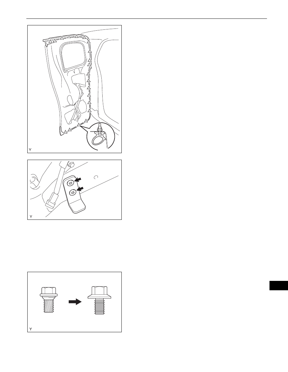
(b) Using a clip remover, disengage the 20 clips, then 

remove the access panel weatherstrip.
NOTICE:
Remove any tape remaining on the door side.

22. REMOVE ACCESS PANEL LOWER LOCK STOP

(a) Using "Torx" socket wrench T40, remove the 2 

screws and access panel lower lock stop.

23. REMOVE ACCESS DOOR OUTSIDE MOULDING 

SUB-ASSEMBLY
HINT:
Use the same procedure as for the LH side (see page 

ET-70

).

24. REMOVE ACCESS DOOR GLASS OUTER 

WEATHERSTRIP
HINT:
Use the same procedure as for the LH side (see page 

ET-43

).

25. REMOVE REAR DOOR GLASS

HINT:
Use the same procedure as for the LH side (see page 

WS-58

).

ADJUSTMENT

HINT:

Before adjusting the door position on vehicles equipped 
with side airbags and curtain shield airbags, be sure to 
disconnect the battery. After the adjustment, inspect the 
SRS warning light, the side airbag system and the curtain 
shield airbag system for normal operation. Then initialize 
both airbag systems.

Use the same procedure for the RH and LH sides.

The procedures described below are for the RH side.

B135540

B135945

Centering Bolt

Standard Bolt

B104980E01

ED–34

ENGINE HOOD / DOOR  –  ACCESS DOOR

ED

Centering bolts are used to mount the door hinge onto the 
vehicle body and door. The door cannot be adjusted with 
the centering bolts on. Substitute standard bolts (with 
washers) for the centering bolts when making 
adjustments.

For bolts without torque specifications, check the standard 
bolt chart (see page 

SS-2

).

1.

INSPECT REAR DOOR
(a) Check that the clearance measurements are within 

the standard ranges.

Standard

Area

Measurement

Area

Measurement

A

4.6 to 7.6 mm 

(0.181 to 0.299 in.)

E

4.6 to 7.6 mm 

(0.181 to 0.299 in.)

B

3.5 to 6.5 mm 

(0.138 to 0.256 in.)

F

4.5 to 7.5 mm 

(0.177 to 0.295 in.)

C

1.1 to 4.1 mm 

(0.043 to 0.161 in.)

G

4.1 to 7.1 mm 

(0.161 to 0.280 in.)

D

4.3 to 7.3 mm 

(0.169 to 0.287 in.)

H

9 to 12 mm 

(0.354 to 0.472 in.)

A

B

C

D

E

F

G

H

B139379E01

ENGINE HOOD / DOOR  –  ACCESS DOOR

ED–35

ED

2.

ADJUST REAR DOOR
(a) Disconnect the cable from the negative battery 

terminal.
CAUTION:
The work must be started at least 90 seconds 
after the ignition switch is turned to OFF and the 
cable is disconnected from the negative battery 
terminal. (The SRS is equipped with a back-up 
power source. If the work is started within 90 
seconds of disconnecting the cable from the 
negative battery terminal and the ignition switch 
being turned to OFF, the SRS may deploy).

(b) Loosen the body side hinge bolts and adjust the 

door position.

(c) Tighten the body side hinge bolts after the 

adjustment.
Torque: 26 N*m (265 kgf*cm, 19 ft.*lbf)

(d) Loosen the door side hinge bolts and adjust the 

door position.

(e) Tighten the door side hinge bolts after the 

adjustment.
Torque: 26 N*m (265 kgf*cm, 19 ft.*lbf)

(f)

Using a screwdriver with its tip wrapped in 
protective tape, disengage the 2 claws and remove 
the 2 roof side inner garnish covers.

B135990

B135991

Protective Tape

B135994E01

ED–36

ENGINE HOOD / DOOR  –  ACCESS DOOR

ED

(g) Remove the 2 bolts.

(h) Disengage the 2 claws and remove the No. 1 roof 

side rail garnish.

(i)

Adjust the striker position by slightly loosening the 
striker mounting screws with "Torx" socket wrench 
T40 and hitting the striker with a plastic hammer 
(upper side).

(j)

Using "Torx" socket wrench T40, tighten the striker 
mounting screws after the adjustment.
Torque: 23 N*m (235 kgf*cm, 17 ft.*lbf)

(k) Adjust the striker position by slightly loosening the 

striker mounting screws with "Torx" socket wrench 
T40 and hitting the striker with a plastic hammer 
(lower side).

(l)

Using "Torx" socket wrench T40, tighten the striker 
mounting screws after the adjustment.
Torque: 23 N*m (235 kgf*cm, 17 ft.*lbf)

(m) Engage the 2 claws and install the No. 1 roof side 

rail garnish.

B135996

B135997

B135992

B135993

B135997


Content   ..  132  133  134  135   ..