Toyota FJ Cruiser (GSJ 10, 15 series). Instruction - part 66
1GR-FE ENGINE CONTROL SYSTEM – SFI SYSTEM
ES–219
ES
INSPECTION PROCEDURE
HINT:
Intelligent tester only:
Malfunctioning areas can be identified by performing the A/F CONTROL function provided in the ACTIVE
TEST. The A/F CONTROL function can help to determine whether the Air-Fuel Ratio (A/F) sensor, Heated
Oxygen (HO2) sensor and other potential trouble areas are malfunctioning.
The following instructions describe how to conduct the A/F CONTROL operation using an intelligent
tester.
(1) Connect an intelligent tester to the DLC3.
(2) Start the engine and turn the tester ON.
(3) Warm up the engine at an engine speed of 2,500 rpm for approximately 90 seconds.
(4) Select the following menu items: DIAGNOSIS / ENHANCED OBD II / ACTIVE TEST / A/F CONTROL.
(5) Perform the A/F CONTROL operation with the engine in an idling condition (press the RIGHT or LEFT
button to change the fuel injection volume).
(6) Monitor the voltage outputs of the A/F and HO2 sensors (AFS B1S1 and O2S B1S2 or AFS B2S1 and
O2S B2S2) displayed on the tester.
HINT:
•
The A/F CONTROL operation lowers the fuel injection volume by 12.5 % or increases the injection
volume by 25 %.
•
Each sensor reacts in accordance with increases and decreases in the fuel injection volume.
Standard
Tester Display
(Sensor)
Injection Volumes
Status
Voltages
AFS B1S1 or AFS B2S1
(A/F)
+25 %
Rich
Less than 3.0
AFS B1S1 or AFS B2S1
(A/F)
-12.5 %
Lean
More than 3.35
O2S B1S2 or O2S B2S2
(HO2)
+25 %
Rich
More than 0.55
O2S B1S2 or O2S B2S2
(HO2)
-12.5 %
Lean
Less than 0.4
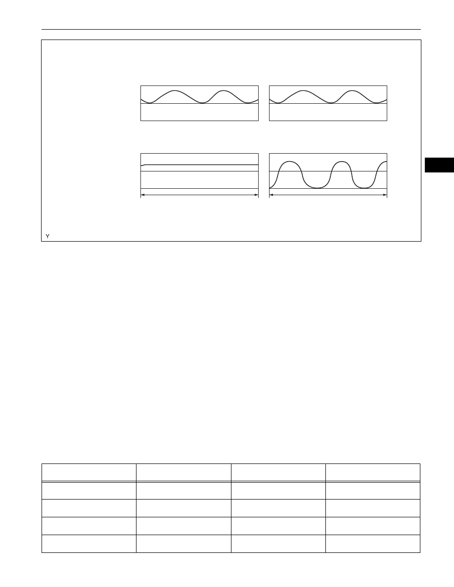
Voltage output when active air-fuel ratio control not performed
Normal Catalyst
Deteriorated Catalyst
Waveform of
HO2 Sensor
behind TWC
Waveform of
A/F Sensor in
front of TWC
3.5 V
3.0 V
1.0 V
0 V
10 seconds
10 seconds
A121610E01