содержание .. 802 803 804 805 ..
Toyota Sequoia (2005). Manual - part 804
BR0TC–06
F13317
F13318
F13319
BR–38
–
BRAKE
REAR BRAKE CALIPER
3205
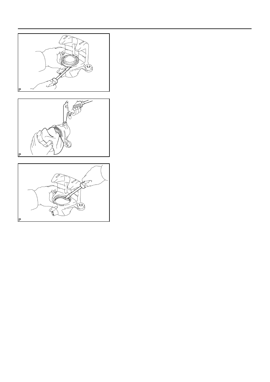
DISASSEMBLY
1.
REMOVE CYLINDER BOOTS
Using a screwdriver, remove the cylinder boot from the caliper.
2.
REMOVE PISTON
(a)
Place a piece of cloth or a similar object between the pis-
ton and caliper.
(b)
Use compressed air to remove the piston from the cylin-
der.
CAUTION:
Do not place your fingers in front of the piston when using
compressed air.
3.
REMOVE PISTON SEAL FROM BRAKE CYLINDER
Using a screwdriver, remove the piston seal from the caliper.
4.
REMOVE CAP AND BLEEDER PLUG
Torque: 11 N·m (110 kgf·cm, 8 ft·lbf)
5.
REMOVE BUSHING, PLUG AND BOOT