содержание .. 789 790 791 792 ..
Toyota Sequoia (2005). Manual - part 791
F19820
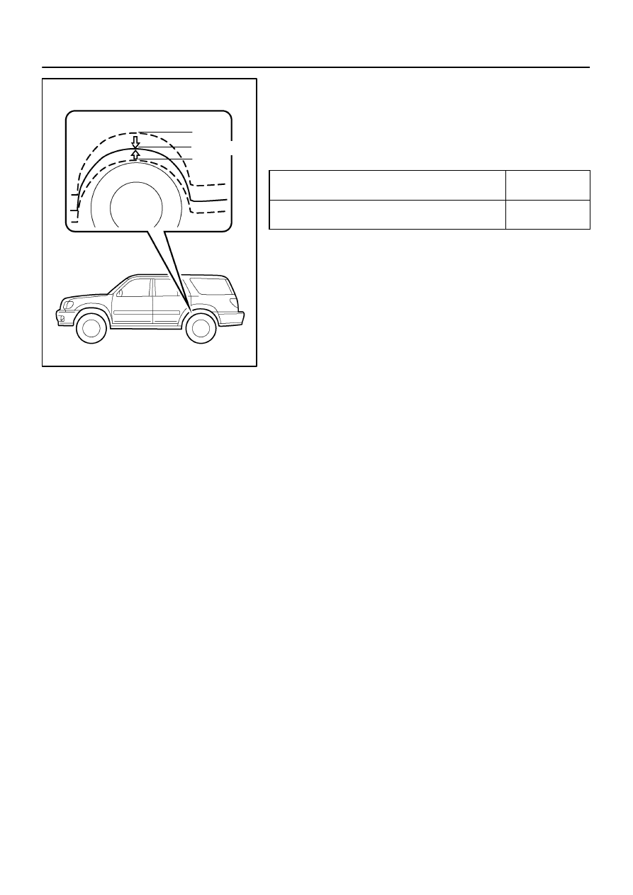
HIGH
NORMAL
LOW
–
SUSPENSION AND AXLE
ELECTRONIC MODULATED AIR SUSPENSION
SA–157
3153
(b)
While adjusting vehicle height in the HIGH position, start
the engine and change the height control switch from the
HIGH position to the NORM position.
Check the time until the height adjustment is completed
and the amount of change in vehicle height.
Adjustment time
From operation of height control switch
to open of exhaust valve.
Approx. 2 sec.
From open of exhaust valve to completion
of height adjustment.
Approx. 30 sec.
Amount of change in vehicle height
HIGH position: 40 mm (1.57 in.)
LOW position:
4WD models: –30 mm (–1.18 in.)
2WD models: –15 mm (–0.59 in.)