содержание .. 765 766 767 768 ..
Toyota Sequoia (2005). Manual - part 767
SA23Q–03
F06635
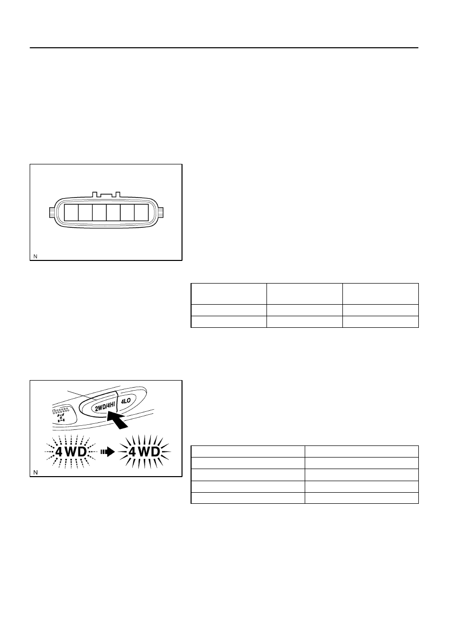
Actuator side:
1
4
2
3
5
6
F19317
2WD/4HI Switch
–
SUSPENSION AND AXLE
A.D.D. CONTROL SYSTEM
SA–61
3057
INSPECTION
1.
INSPECT A.D.D. ACTUATOR
(a)
Disconnect the actuator connector.
(b)
Measure the resistance between terminals 2 and 6.
Standard resistance: 0.3 – 100
Ω
(c)
Measure the resistance between terminal 2 or 6 and body
ground.
Standard resistance: More than 0.5 M
Ω
If the resistance value is not as specified, replace the actuator
assembly.
2.
INSPECT A.D.D. ACTUATOR OPERATION
Apply battery positive voltage between terminals 2 and 6, and
check the actuator operation by sound, A.D.D. status and conti-
nuity between terminals 3 and 4.
Battery voltage
applied terminal
3 – 4 terminals continuity
A.D.D.
status
2 (+) – 6 (–)
Continuity
Connected
2 (–) – 6 (+)
No continuity
Disconnected
If the operation is not as specified, replace the actuator assem-
bly.
3.
INSPECT LIMIT SWITCH CONTINUITY
(a)
Connect the actuator connector.
(b)
Push the 2WD/4HI switch and check that the 4WD indica-
tor light comes on after it is blinking.
(c)
Check the A.D.D. actuator operation by sound.
(d)
Disconnect the actuator connector.
(e)
Check the continuity between each terminal, as shown in
the chart.
Tester connected terminal number
Specified condition
1 – 3
No continuity
1 – 4
No continuity
3 – 5
Continuity
4 – 5
No continuity
(f)
Connect the actuator connector.