содержание .. 694 695 696 697 ..
Toyota Sequoia (2005). Manual - part 696
B17467
SF1XJ–01
D13872
Hand–Held Tester
DLC3
CAN VIM
–
SFI
THROTTLE BODY
SF–39
2773
THROTTLE BODY
ON–VEHICLE INSPECTION
1.
REMOVE THROTTLE BODY COVER
2.
INSPECT SYSTEM OPERATION
(a)
Inspect the throttle control motor for operating sound.
(1)
Turn the ignition switch ON.
(2)
When depressing the accelerator pedal, check the
running sound of the motor. Also, check that there
is no friction sound.
If operation is not as specified, check the throttle control motor
(see step 3), wiring and ECM.
(b)
Inspect the accelerator pedal position sensor.
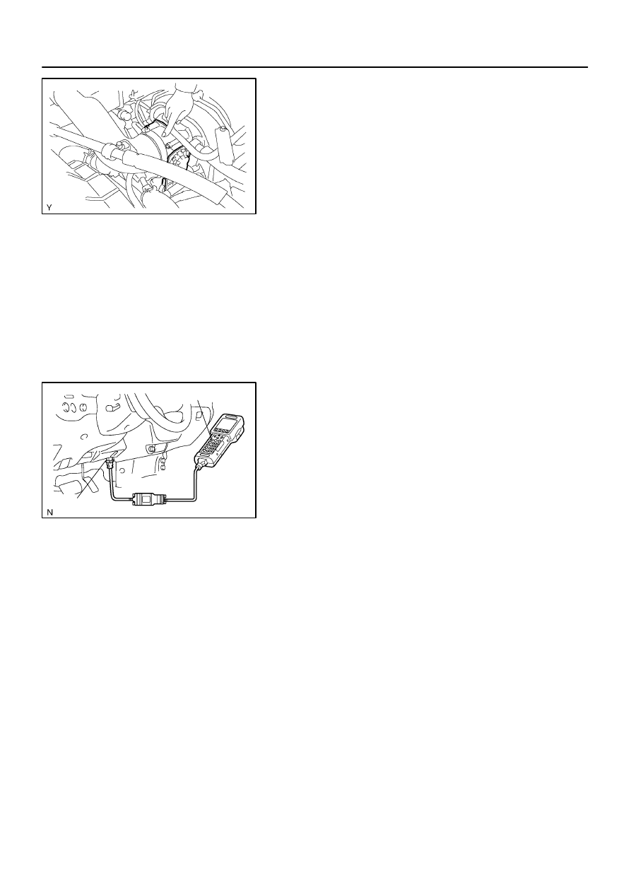
(1)
Connect a hand–held tester to the Controller Area
Network Vehicle Interface Module (CAN VIM). Then
connect the CAN VIM to the Date Link Connector 3
(DLC3).
(2)
Check that the MIL does not light up.
(3)
When turning the accelerator pedal position sensor
lever to the full–open position, check that the
throttle valve opening percentage (THROTTLE
POS) of the CURRENT DATA showns the standard
value.
Standard throttle valve opening percentage:
60% or more
If operation is not as specified, check that the accelerator pedal
position sensor (see page
If not using a hand–held tester, measure the voltage between
terminals (VTA1–E2, VTA2–E2) of the ECM connector (See
page
(c)
Inspect the idle speed.
(1)
Start the engine and check that the MIL does not
light up.
(2)
Allow the engine to warm up to normal operating
temperature.
(3)
Turn the A/C compressor ON to OFF, and check the
idle speed.
Idle speed (Transmission in neutral): 700
±
50 rpm
NOTICE:
Perform inspection without an electrical load.
(d)
After checking the above (a) to (c), perform the driving test
and check that there is no sense of incongruity.