содержание .. 673 674 675 676 ..
Toyota Sequoia (2005). Manual - part 675
A04211
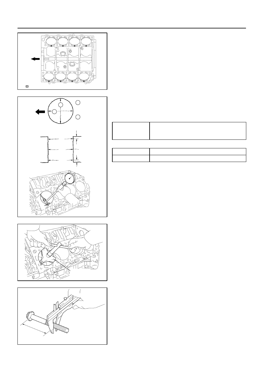
Mark 1, 2 or 3
Front
No.2
No.4
No.6
No.8
No.1
No.3
No.5
No.7
:
A04262
A04851
A05181
1
2
B
C
A
Thrust
Direction
Axial
Direction
10 mm
(0.39 in.)
10 mm
(0.39 in.)
Front
1
2
1
A04852
Ridge
Reamer
A05138
50 – 64 mm (1.97 – 2.52 in.)
EM–110
–
ENGINE MECHANICAL
CYLINDER BLOCK
2689
(c)
Inspect the cylinder bore diameter.
HINT:
There are 3 sizes of the standard cylinder bore diameter,
marked ”1”, ”2” and ”3” accordingly. The mark is stamped on the
top of the cylinder block.
Using a cylinder gauge, measure the cylinder bore diame-
ter at positions A, B and C in the thrust and axial direc-
tions.
Standard diameter:
STD
Mark ”1”
94.002 to 94.010 mm (3.7009 to 3.7012 in.)
STD
Mark 1
Mark ”2”
94.002 to 94.010 mm (3.7009 to 3.7012 in.)
94.010 to 94.023 mm (3.7012 to 3.7017 in.)
Mark 2
Mark ”3”
94.010 to 94.023 mm (3.7012 to 3.7017 in.)
94.023 to 94.031 mm (3.7017 to 3.7020 in.)
Maximum diameter:
STD
94.231 mm (3.7099 in.)
O/S 0.50
94.731 mm (3.7296 in.)
If the diameter is greater than maximum, rebore all the 8 cylin-
ders and replace all the 8 pistons. (See page
) If neces-
sary, replace the cylinder block.
(d)
Remove the cylinder ridge.
If the wear is less than 0.2 mm (0.008 in.), using a ridge reamer,
grind the top of the cylinder.
(e)
Using vernier calipers, measure the thread outside diam-
eter of the main bearing cap bolt.
Standard diameter:
10.760 to 10.970 mm (0.4236 to 0.4319 in.)
Minimum diameter: 10.40 mm (0.4094 in.)
If the diameter is less than minimum, replace the cap bolt.