содержание .. 671 672 673 674 ..
Toyota Sequoia (2005). Manual - part 673
A05086
Pry
A05100
A05104
A05105
EM–102
–
ENGINE MECHANICAL
CYLINDER BLOCK
2681
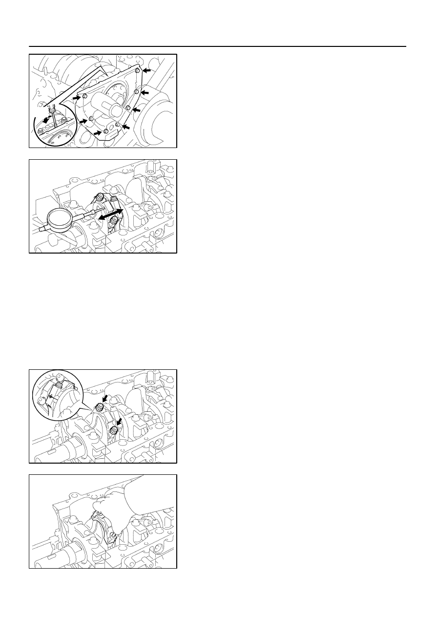
18.
REMOVE REAR OIL SEAL RETAINER
(a)
Remove the 7 bolts.
(b)
Using a screwdriver, remove the oil seal retainer by prying
the portion between the oil seal retainer and main bearing
cap.
(c)
Remove the O–ring.
19.
CHECK CONNECTING ROD THRUST CLEARANCE
Using a dial indicator, measure the thrust clearance while mov-
ing the connecting rod back an forth.
Standard thrust clearance:
0.160 to 0.290 mm (0.0063 to 0.0114 in.)
Maximum thrust clearance: 0.35 mm (0.0138 in.)
If the thrust clearance is greater than maximum, replace the
connecting rod assembly(s). If necessary, replace the crank-
shaft.
Connecting rod thickness:
22.880 to 22.920 mm (0.9008 to 0.9024 in.)
20.
REMOVE CONNECTING ROD CAPS AND CHECK OIL
CLEARANCE
(a)
Check the matchmarks on the connecting rod and see it
cap to ensure correct reassembly.
(b)
Remove the 2 connecting rod cap bolts.
(c)
Using the 2 removed connecting rod cap bolts, remove
the connecting rod cap and lower bearing by wiggling the
connecting rod cap right and left.
HINT:
Keep the lower bearing inserted with the connecting rod cap.
(d)
Clean the crank pin and bearing.
(e)
Check the crank pin and bearing for peeling and
scratches.
If the crank pin or bearing is damaged, replace the bearings. If
necessary, replace the crankshaft.