Toyota Sequoia (2005). Manual - part 1003


  Главная      Automobile - Toyota     Toyota Sequoia - Repair manual 2005 year


поиск по сайту           правообладателям


содержание   ..  1001  1002  1003  1004   ..


Toyota Sequoia (2005). Manual - part 1003


212

SEQUOIA (EM00Z0U)

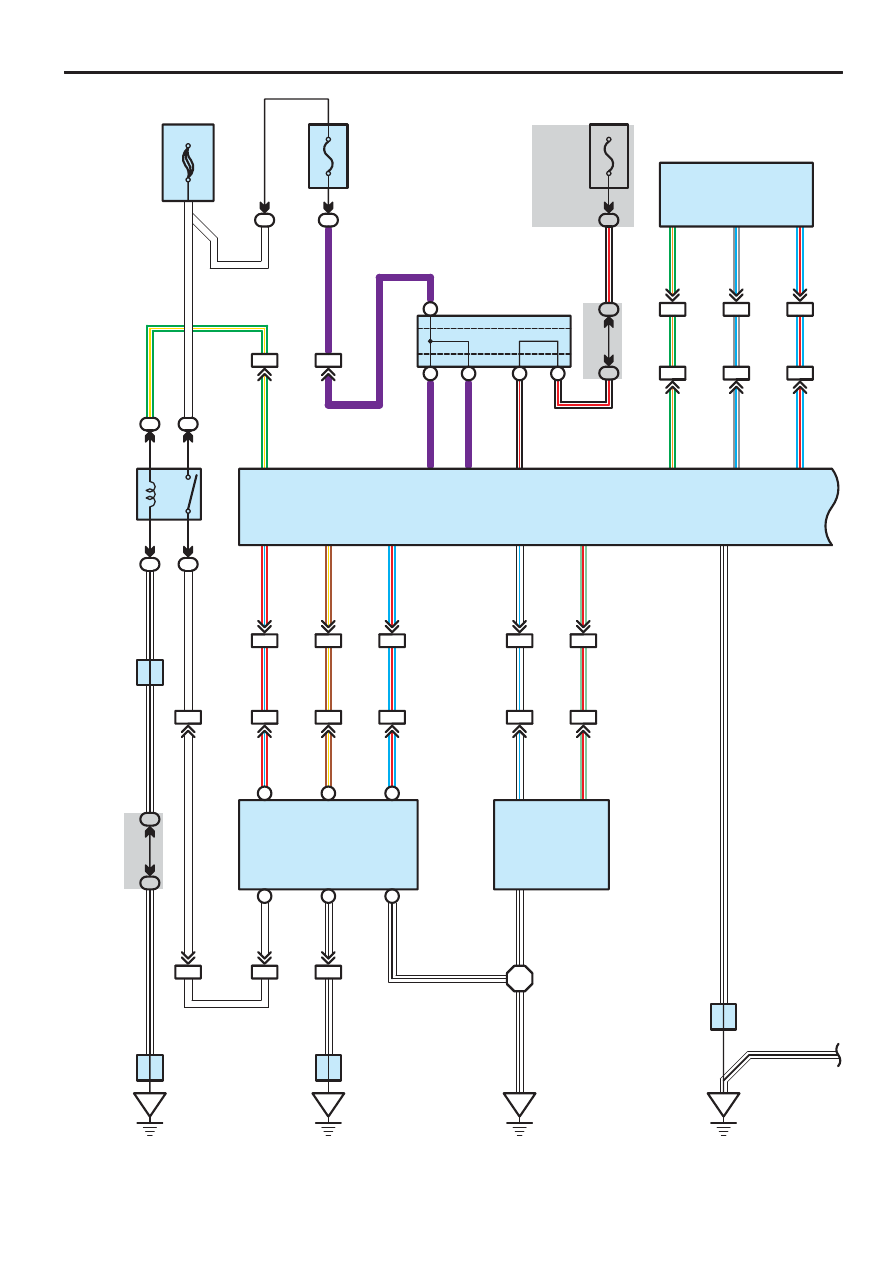
Electric Modulated Air Suspension

2

3

1

5

2

2

2

2

9

50A AI

R SUS

IA1

25

5

25

RC

BAT

A

B

A

B

B

C

IA5

5

10A
AIR
SUS
No. 2

2

2

2

IN1

15

BM2

3

BM2

2

BJ

A

R–

L

R–

L

R–

L

W–B

W–B

20

RM+

A

3

A

2

IN1

6

BM2

4

BR–

Y

BR–

Y

BR–

Y

21

RM–

A

4

IN1

4

BM2

5

L–

R

L–

R

L–

R

1

SLEX

B

1

W

A

1

BM2

1

IC4

8

IA1

21

F1

0

24

B

IE

A

W–B

1K

12

1F

9

A

A

J2

8

H1

3

(A

), H14

(B

)

IN1

14

BM1

8

W–L

W–L

W–L

4

SLRL

IN1

13

BM1

4

LG–

R

LG–

R

LG–

R

3

SLRR

1

3

2

BI

W–B

B

2

W–B

W–B

H1

6

G–

Y

V

V

V

W

W

G–

Y

W–B

W

W–B

W

W

G–Y

W

V

V

22

IF

A

W–B

GND

W–B

J12

J19

J 8

10

IG

A

A

A

A

B–

R

J37(A), J38(B)

3A

8

3C

8

10A
ECU–IG

1F

4

BM1

5

IN1

18

G–

O

G–

O

BM1

6

IN1

17

GR

L

GR

L

BM1

7

IN1

16

L–

R

L–

R

1

SHB

2

SHRL

3

SHG

G–

O

GR

L

L–

R

H15

15

SBL

17

SHRL

19

SGL

B–

R

B–R

1

AI

R SUS

Re

la

y

S25

Fusi

bl

e L

ink B

lock

Junction
Connector

Junction
Connector

Junction
Connector

Juncti

on

C

onnector

Junction Connector

Suspension Control ECU

H

e

ight C

ontr

o

l C

o

m

p

re

ssor

H

e

ight C

ontr

o

l V

a

lv

e

Height Control Sensor
Rear LH

(IG)

(BAT)

W–B

SEQUOIA (EM00Z0U)

213

LO

HI

2

3

4

HSW

LWS

E

H1

2

4

3

IM

13

UPSW

32

DNSW

12

TD

SIL

15A
STOP

1F

2

W

4

1

S14

4A

1

4A

11

27

STP

G–Y

G–Y

G–

Y

D 6

B

W

7

29

CANH

D

2

D

6

14

CANH

CANL

CANL

28

W

1

T 5

1 B

2

C

2

C

1

A

2

A

1

B

CANL

ENG–

ENG+

CANH

J5

3

(A

), J

5

4

(B

), J

5

5

(C

), J

5

6

(D

)

14

16

34

33

W

R

W

L

W

R

E 5

G

IL2

6

IL2

7

CANL

CANH

2

6

S 1

VSC+

VSC–

7

11

W

LL

W

3B

4

3C

4

30

SIL

G–

R

G

R

31

R

LG

P

HEI

G

HT

CO

NT

RO

L

MA

N

U

H1

7

B–L

GR–R

GR

R

B–

L

P

LG

R

W–B

W–B

BR–

B

W

L–

B

S25

DOOR

11

VN

26

LO

9

NR

8

HI

Data Link Connector 3

Engine Control
Module

Skid Control ECU
with Actuator

S

top L

ight S

W

Tr

ansl

a

te E

C

U

Suspension Control ECU

H

e

ight C

ontr

o

l S

W

H

e

ight  C

ontr

o

l M

ode S

e

le

ct S

W

Juncti

on C

onnector

(BAT)

W–B

214

SEQUOIA (EM00Z0U)

Electric Modulated Air Suspension

LO

MA

N

U

N

HI

C 6

10A
IGN1

1H

11

16

15

14

13

24

K

D

B

RRCY

RLCY

2

2

3

3

R–

W

R–

W

R–

W

R–

W

8 A

B–

O

1

7 C

A

B–

O

1

A

J

B

C

J4

4

(A

), J

4

5

(B

)

J2

9

(A

), J

3

0

(B

)

D 9

D 8

D1

7

D1

6

A

22

C

12

1

1

PCTY

DCTY

LG–

B

GR

R

LG–

B

A

N

B

G

A

G

B

N

GR

R

D1

4

D1

5

J4

4

(A

), J

4

5

(B

)

J2

9

(A

), J

3

0

(B

)

R

LG

P

B–L

GR–R

LG

P

B–

L

GR

R

B–

O

R

ACTY

20 B

C 5

I19

32

A

24

13

MPX2

B1

0

(A

), B

1

1

(B

)

B 5(A), B 6(B), B 7(C)

B 9

R

W–B

BD2

7

LG–

R

LG–R

LG–R

BF1

6

LG–

R

MPX1

2

1

CTYE

BDCY

20 A

7

3

MPX+

MPX–

LG–

B

A

B

B

A

H

L–

Y

2 B

J3

3

(A

), J

3

4

(B

)

31

Body ECU

B

a

ck D

oor

 C

our

tesy S

W

Ba

ck

 Do

o

r ECU

C

o

m

b

inati

o

n

Me

te

r

C

o

m

b

inati

on M

e

ter

D

iode

(Inter

ior

 L

ight N

o

. 1

)

D

iode

(Inter

ior

 L

ight N

o

. 2

)

D

oor

 C

our

tesy S

W

Fr

ont L

H

D

oor

 C

our

tesy S

W

Fr

ont R

H

D

oor

 C

our

tesy S

W

R

ear

 L

H

D

oor

 C

our

tesy S

W

R

ear

 R

H

Integr

ati

on C

ontr

o

l

and P

anel

Juncti

on C

onnector

Juncti

on C

onnector

Juncti

on C

onnector

Juncti

on C

onnector

Juncti

on C

onnector

(IG)

SEQUOIA (EM00Z0U)

215

The electric modulated air suspension with height control, is a system designed to maintain a constant ride height by
means of an electro–pneumatic system in the rear suspension – to cope with change in load due to possible change in the
number of people and/or the weight of cargo the vehicle has to carry. With three driver’s–choice height–control switches
on the console, the driver can set ride height to any one of the three different ride height modes (High, normal and low):
”High mode” for rough terrain and ”Low mode” for passenger to get on or get off, and for cargo to be loaded or unloaded.

This system has five basic controls as shown below:

Auto leveling control
This control maintains a constant rear vehicle ride height regardless of change in load due to possible change in the
number of passengers and/or the weight of cargo the vehicle has to carry.

Ride height switchover control
This control switches over height mode to the mode selected by the height control switch.

High mode (+ 40 mm / 1.6 in.)

Low mode ( – 30 mm / 1.2 in. : 4WD) ( – 15 mm / 0.6 in. : 2WD)

Speed sensing control
Regardless of the initial height mode setting, ”High mode” or ”Low mode,” this control automatically switches over vehicle
height mode to the optimum  ”Normal mode”:

When the vehicle speed exceeds 30 km/h with height mode set to ”High mode,” or;

When the vehicle speed exceeds 12 km/h with height mode set to ”Low mode.”

Subsequent control after ignition switch off
After the ignition switch is turned OFF, this control lowers the rear vehicle ride height to offset rear vehicle ride height
elevation due to passengers getting off, etc.

Height control OFF control
Pressing the height control mode select SW turns the system OFF (MANU indicator light off), making it possible for the
vehicle to be jacked up or towed.

  :  Parts Location

Code

See Page

Code

See Page

Code

See Page

B5

A

42

E5

43

J33

A

44

B6

B

42

F10

22, 40

J34

B

44

B7

C

42

H12

43

J37

A

44

B9

46

H13

A

46

J38

B

44

B10

A

46

H14

B

46

J44

A

44

B11

B

46

H15

46

J45

B

44

C5

42

H16

46

J53

A

44

C6

42

H17

43

J54

B

44

D6

43

I19

43

J55

C

44

D8

46

J8

44

J56

D

44

D9

46

J12

44

S1

41

D14

46

J19

46

S14

45

D15

46

J28

41

S25

45

D16

46

J29

A

44

T5

45

D17

46

J30

B

44

: Relay Blocks

Code

See Page

Relay Blocks (Relay Block Location)

2

26

Engine Room R/B No.2 (Engine Compartment Left)

: Junction Block and Wire Harness Connector

Code

See Page

Junction Block and Wire Harness (Connector Location)

1F

33

Cowl Wire and Instrument Panel J/B (Lower Finish Panel)

1H

33

Cowl Wire and Instrument Panel J/B (Lower Finish Panel)

1K

33

Engine Room Main Wire and Instrument Panel J/B (Lower Finish Panel)

3A

36

Cowl Wire and Sub J/B No.3 (Upper the Accelerator Pedal)

3B

36

Cowl Wire and Sub J/B No.3 (Upper the Accelerator Pedal)

3C

36

Cowl Wire and Sub J/B No.3 (Upper the Accelerator Pedal)

4A

38

Cowl Wire and Sub J/B No.4 (Upper the Accelerator Pedal)

System Outline


содержание   ..  1001  1002  1003  1004   ..