Toyota Sequoia (2005). Manual - part 1002


  Главная      Automobile - Toyota     Toyota Sequoia - Repair manual 2005 year


поиск по сайту           правообладателям


содержание   ..  1000  1001  1002  1003   ..


Toyota Sequoia (2005). Manual - part 1002
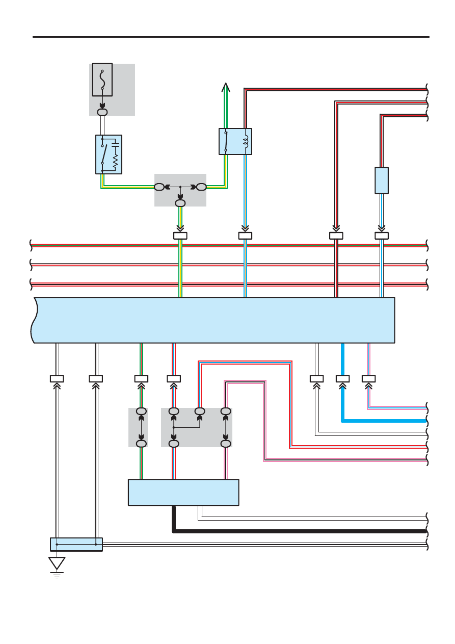


196

SEQUOIA (EM00Z0U)

ABS, TRAC and VSC

(4WD)

IL2

12

+BO

P–

L

B–

R

B–

R

13

IG1

IL1

1

15A
STOP

1F

2

G–Y

G–

Y

39

STP

IL2

13

G–

Y

IL1

15

B–

R

W–L

W–L

22

BZ

1

2

IL1

7

BSW

L–

O

L–

O

B 8

V 5

B

u

zzer

IG

IL2

7

IL2

6

IL1

24

3B

4

3E

4

IL1

26

R–G

S 1

7

13

12

1

32

15

40

2

6

R–

L

P–

B

G–

R

W–B

W–B

G–

R

R–

L

R–

L

G–

R

W

L

W

L

41

R–G

B–R

B–R

B–R

G–

Y

B–

R

L

W

R–L

P–B

A

D 6

IL1

9

IL1

17

GND1

GND2

D/G

TS

CANL

CANH

W–B

W–B

High Mounted Stop Light

A

A

4

1

3

2

G–

W

SIL

TC

TS

W

1

4

38

W–R

R–B

4C

1

1

4A

1 4B

W–R

R–B

P–L

W–B

W–B

R–

L

Rear Combination Light RH

Rear Combination Light LH

S14

W–B

(4WD)

4C

6

4A

6

4B

6

W

B

4B

5

4A

5

P–

B

6

14

CANH

CANL

B

W

B

rake Inhi

bi

t R

e

la

y

Data Link Connector 3

Skid Control ECU with Actuator

S

top L

ight S

W

VSC W

a

rn

in

g

 Bu

zz

e

r

Junction
Connector

J18

(BAT)

SEQUOIA (EM00Z0U)

197

J3

7

(A

), J

3

8

(B

)

(4W

D

)

A B

10A
ECU–IG

B

A

A

A

1F

4

B–

R

A

A

A

A

IA1

23

2

1

IA5

9

IG

WT

IG1

2

3

11

19

18

7

11

27

28

40

24

38

1

1

Y–

L

Y–

L

W–B

OO

O

P–

B

R–

L

W

L

O

O

O

R–

G

B–

R

B–

R

A B

A

O

O

S 7

B 1

T 5

LVL2

GND

TC

TS

VSC–

VSC+

SS1+

SS1–

33

P

L–

Y

29

CD

BR–

Y

IG

SS1–

SS1+

ESS

BAT

P–

L

9

20

TRIG

10

TRIG

Y

W–L

Y

W–L

IND

37

W–R

BRL

39

R–B

20

F23

P

(4W

D

)

IND2

BR–

Y

C B

C A

6

2

IG4

9

L–

R

L–

Y

L

R

P 1

A

A

A

J43

W–B

A

26

L–

W

CSW

4B

8

4A

18

D

8

A

10

GND

CPU

L–

W

O

I19

(A

), I22

(D

)

(4W

D

)

(4WD)

B–

R

B–

R

3A

8

3C

8

B–

R

3B

9

3C

9

(4W

D

)

6

7. 5A
RAD
NO. 2

7

15A
GAUGE

8

1D

7

IPO

J5

1

(A

), J

5

2

(B

)

L–

Y

(4W

D

)

B

W

B

rake Fl

ui

d L

e

vel

W

a

rn

ing S

W

Integr

ati

on C

ontr

o

l

and P

anel

Juncti

on C

onnector

Junction Connector

P

a

rk

/N

eutr

a

l P

o

si

tion S

W

Steering Angle Sensor

Translate ECU

Juncti

on C

onnector

4WD Control ECU

W

B

W–B

P–L

R–B

W–R

P–B

R–L

W

L

B–R

B–R

B–R

R–G

(4WD)

(ACC)

(IG)

(IG)

198

SEQUOIA (EM00Z0U)

ABS, TRAC and VSC

W

W–B

(4W

D

)

(4W

D

)

Y–

B

1

4

LG–

R

LG–

R

P 2

PKB2

T 5

W–B

IG4

21

9

10

IG4

18

4B

7

W–B

Y–

B

Y

G

31

EXI2

T 4

(4W

D

)

4D

4

4B

4

(4W

D

)

W–B

A

A

(4WD)

(4W

D

)

(4W

D

)

C

2

C

1

2 D

D

1

A

2

A

1

B

2

B

1

CANL

ENG–

ENG+

28

29

CANL

CANH

CANH

14

16

34

33

W

R

W

G

W

L

W

B

(

2

)

(

2

)

E 5

B

S25

J5

3

(A

), J

5

4

(B

), J

5

5

(C

), J

5

6

(D

)

4A

17

 2 : Electric Modulated Air Suspension System

Engine Control Module

P

a

rk

ing B

rake S

W

Tr

ansfer

 S

h

ift A

ctuator

Translate ECU

Suspension Control ECU

Juncti

on C

onnector

J4

1

Juncti

on

C

onnector

SEQUOIA (EM00Z0U)

199

ABS Operation

This system controls the respective brake fluid pressures acting on the disc brake cylinders of the right front wheel, left front
wheel, and rear wheels when the brakes are applied in a panic stop so that the wheels do not lock.
This results in improved directional stability and steerability during panic braking.

1. Input Signal

(1) Speed sensor signal

The speed of the wheels is detected and input to TERMINALS FL+, FR+, RL+ and RR+ of the skid control ECU with
actuator.

(2) Stop light SW signal

A signal is input to TERMINAL STP of the skid control ECU with actuator when the brake pedal is depressed.

2. System Operation

During sudden braking, the skid control ECU with actuator which has signals input from each sensor lets the hydraulic
pressure acting on each wheel cylinder escape to the reservoir.
The pump inside the skid control ECU with actuator is also operating at this time and it returns the brake fluid from the
reservoir to the master cylinder, thus preventing locking of vehicle wheels.
If the skid control ECU with actuator judges that the hydraulic pressure acting on the wheel cylinder is insufficient, the current
acting on the solenoid is controlled and the hydraulic pressure is increased.
Holding of the hydraulic pressure is also controlled by the ECU, by the same method as above, by repeated pressure
reduction. Holding and increase are repeated to maintain vehicle stability and to improve steerability during sudden braking.

VSC Operation

The vehicle could be in an extreme over steering or under steering tendency due to unexpected accidents, road conditions,
vehicle speed, or by other external factors. In such a case, this system automatically controls the engine output and the
braking to each wheel, to decrease the extreme over steering and under steering.

To decrease extreme over steering tendency

When the system determines that the over steering tendency is large, the system applies brakes to the outer wheels
according to the degree of over steering, and creates a moment towards the outer side of the vehicle, to decrease the
tendency of over steering. Also, when the brakes are applied, the vehicle speed decreases while the stability increases.

To decrease extreme under steering tendency

When the system determines that the under steering tendency is large, the system applies brakes to the front or rear wheels
according to the degree of under steering, to decrease the tendency of under steering.
When the VSC operated, the skid control ECU with actuator sends a signal and the slip indicator in the instrumental cluster
will flash and a buzzer will sound to warn the driver than the tire grip is at its limit.

Active Traction Control (4WD)

While driving with the 4WD mode, the active TRAC system helps control the spinning of the wheels which may occur when
accelerating on a snowy road or during severe off–road driving, by controlling the brake fluid pressure of each wheel. The
system distributes the traction lost by slipping to each wheel, which produces a strong LSD effect.  When the active TRAC is
in use, the skid control ECU with actuator sends a signal and the slip Indicator in the instrumental cluster will flash and a
buzzer will sound to notify the driver.

Traction Control Operation (2WD)

Estimating the vehicle speed from the rear wheel speed, comparing it with the front, driving wheel speed and judging the grip
condition of the driving wheels. From the estimated vehicle speed, target speed of the driving speed will be set. When the
front, driving wheel speed exceeds the control starting speed, it judges that the tire slip is occurred and performs the fuel cut
cylinder number control and brake control and then adjust to make the front wheel speed become the traction control target
speed. Controlling of the traction control will be completed when the vehicle move on to the road where the driving wheels
will not have a tire slip or when the driver decelerate.

System Outline


содержание   ..  1000  1001  1002  1003   ..