Toyota Tundra (2015 year). Manual - part 3049


  Index      Toyota     Toyota Tundra (2015 year) - Service and Repair Manual


Search            copyright infringement  


Content   ..  3047  3048  3049  3050   ..


Toyota Tundra (2015 year). Manual - part 3049


2. DISPOSE OF LOWER NO. 1 INSTRUMENT PANEL AIRBAG ASSEMBLY (WHEN NOT

INSTALLED IN VEHICLE)

NOTICE:

Be sure to follow the procedure detailed below when deploying the airbag.

HINT:

Prepare a battery as the power source to deploy the airbag.

.

(b) Remove the lower No. 1 instrument panel airbag 


.

CAUTION:

When removing the lower No. 1 instrument panel airbag, wait at least 90 seconds after the ignition switch is
turned off and the cable is disconnected from the negative (-) battery terminal before starting work.
When storing the lower No. 1 instrument panel airbag, keep the airbag deployment side facing upward.

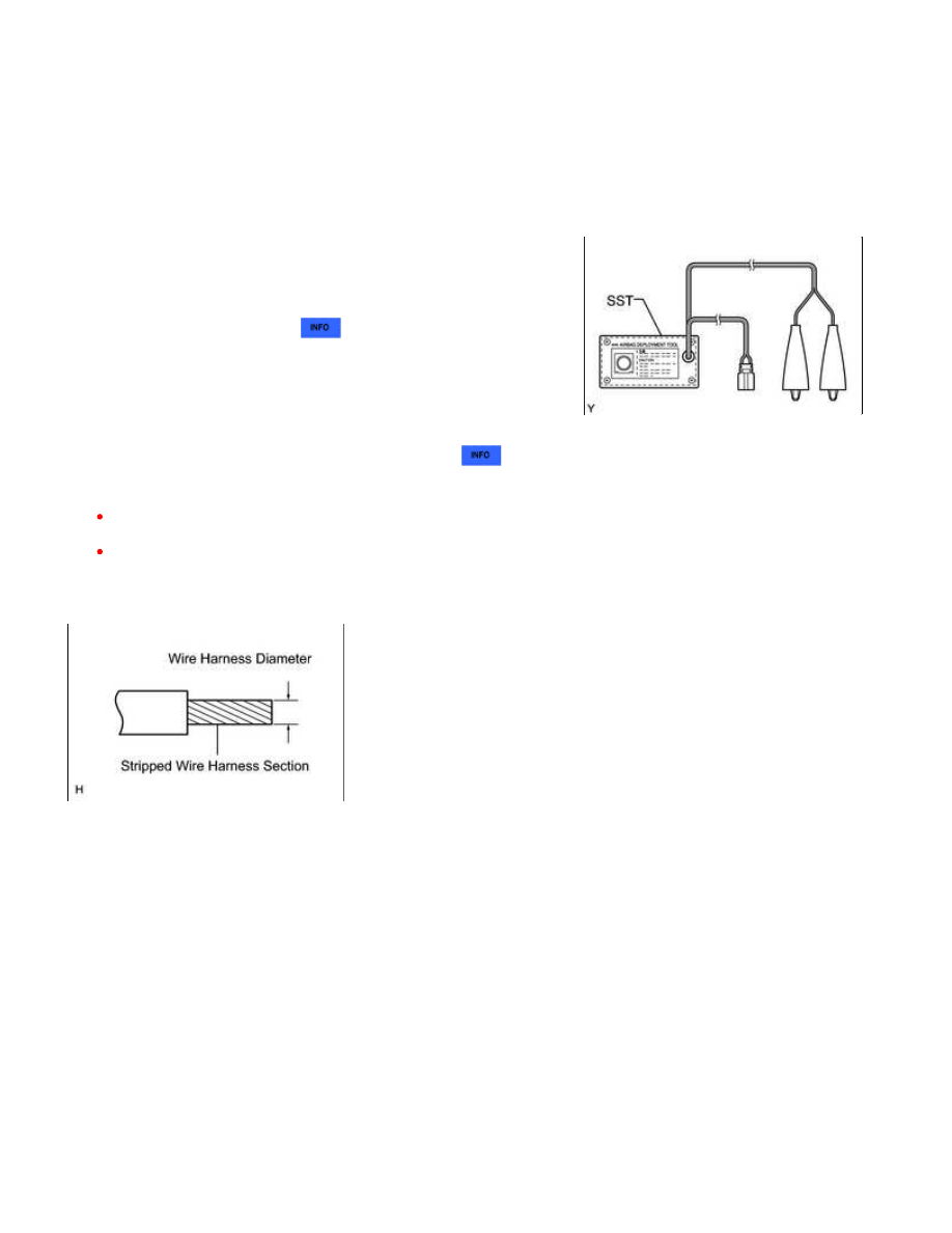
(c) Using a service-purpose wire harness for the vehicle, tie down the lower No. 1 instrument panel airbag to a

tire.

2

 or more (0.00192 in. 

2

 or more)

CAUTION:

If the wire harness is too thin or an alternative object is used to tie down the lower No. 1 instrument panel

 (0.00192 in. 

2

 ).

HINT:

2

 / 4

(1) Position the lower No. 1 instrument panel airbag inside a tire with the airbag deployment side facing

inside.

SUPPLEMENTAL RESTRAINT SYSTEM: DRIVER SIDE KNEE AIR...

Tire size:

Must exceed the following dimensions

Width

185 mm (7.28 in.)

Inner diameter

360 mm (14.2 in.)

(2) Tie the lower No. 1 instrument panel airbag to the tire with several wire harnesses.

CAUTION:

Make sure that the wire harnesses are tight. If there is slack in the wire harnesses, the lower No. 1
instrument panel airbag may become loose due to the shock when the airbag is deployed.
Always tie down the lower No. 1 instrument panel airbag with the airbag deployment side facing inside the
tire.

NOTICE:

As the tire may be damaged by the airbag deployment, use a tire that you are planning to throw away.

(d) Connect SST connector to the lower No. 1 instrument panel

airbag.

SST: 09082-00780

(e) Place tires.

SUPPLEMENTAL RESTRAINT SYSTEM: DRIVER SIDE KNEE AIR...

(1) Place at least 2 tires under the tire which the lower No. 1 instrument panel airbag is tied to.

(2) Place at least 2 tires over the tire which the lower No. 1 instrument panel airbag is tied to. The top tire

should have a disc wheel installed.

NOTICE:

Do not place SST connector under the tires because it could be damaged.
As the disc wheel may be damaged by the airbag deployment, use a disc wheel that you are planning to
throw away.
As the tires may be damaged by the airbag deployment, use tires that you are planning to throw away.

(3) Tie the tires together with 2 wire harnesses.

CAUTION:

Make sure that the wire harnesses are tight. Looseness in the

wire harnesses results in the tires coming free due to the shock
when the airbag is deployed.

(f) Connect SST connector.

SST: 09082-00700

NOTICE:

To avoid damaging SST connector and wire harness, do not lock

(3) Press SST activation switch to deploy the airbag.

CAUTION:

SUPPLEMENTAL RESTRAINT SYSTEM: DRIVER SIDE KNEE AIR...

When deploying the airbag, make sure that no one is near the tires.

HINT:

CAUTION:

The lower No. 1 instrument panel airbag becomes extremely hot
when the airbag is deployed, so do not touch it for at least 30
minutes after deployment.
Use gloves and safety glasses when handling a lower No. 1
instrument panel airbag with a deployed airbag.
Do not apply water to a lower No. 1 instrument panel airbag with
a deployed airbag.
Always wash your hands with water after completing the
operation.

(1) Remove the lower No. 1 instrument panel airbag from the

tire.

(2) Place the lower No. 1 instrument panel airbag in a plastic

SUPPLEMENTAL RESTRAINT SYSTEM: DRIVER SIDE KNEE AIR...


Content   ..  3047  3048  3049  3050   ..