Toyota Tundra. Manual - part 935
 

  Index      Toyota     Toyota Tundra (2007-2010 year) - Service and Repair Manual


Search            copyright infringement  


Content   ..  933  934  935  936   ..


Toyota Tundra. Manual - part 935


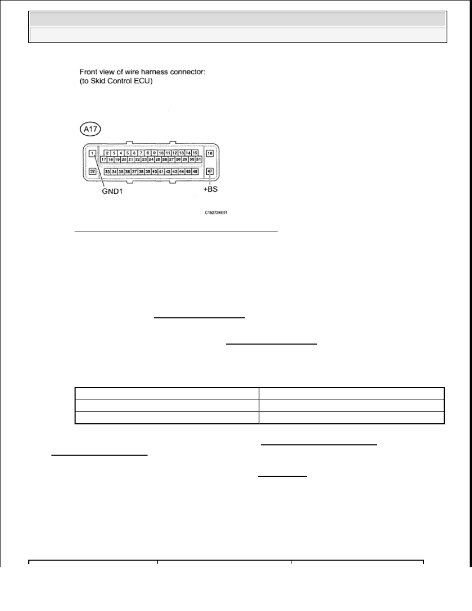
Fig. 59: Identifying A17 ECU Connector Terminals 
Courtesy of TOYOTA MOTOR SALES, U.S.A., INC. 

NG: REPAIR OR REPLACE HARNESS OR CONNECTOR  

OK: Go To Next Step  

4. RECONFIRM DTC 

a. Clear the DTCs (See DTC CHECK/CLEAR ).  

b. Start the engine.  

c. Check if the same DTCs are output (See DTC CHECK/CLEAR ). 

Result  

RESULT TABLE 

B: USE SIMULATION METHOD TO CHECK (See HOW TO PROCEED WITH 
TROUBLESHOOTING
 ) 

A: REPLACE VSC ACTUATOR ASSEMBLY (See REMOVAL ) 

DTC C1247/47: STROKE SENSOR MALFUNCTION 

DESCRIPTION 

Detects a problem with booster vacuum pressure and enters assist control. 

DTC DETECTION CONDITION TABLE 

Result

Proceed to

DTC is output

A

DTC is not output

B


2009 Toyota Tundra 

2009 BRAKES Brake Control - Tundra


WIRING DIAGRAM 

Fig. 60: Identifying Stroke Sensor Malfunction - Wiring Diagram 
Courtesy of TOYOTA MOTOR SALES, U.S.A., INC. 

INSPECTION PROCEDURE 

1. READ VALUE USING TECHSTREAM (STROKE SENSOR) 

a. Connect the Techstream to the DLC3.  

b. Turn the ignition switch to ON.  

c. Run the engine until the engine reaches 3,000 rpm, and return it back to idle. 

HINT: 

Rev up the engine to ensure a sufficient vacuum. 

d. Select the Data List mode on the Techstream. 

ABS/VSC/TRAC  

DTC Code

DTC Detection Condition

Trouble Area

C1247/47

When either condition below is 
met: 

1. When the output becomes 

4.7 V or more or 0.2 V or 
less per 100 msec.  

2. When the output does not 

return to 2.5 V even when 
0.5 sec. or more elapse, in 
spite of no change in brake 
operation.  

Brake booster  

Pedal stroke sensor  

Pedal stroke sensor circuit  

Skid control ECU  

NOTE:

When replacing the VSC actuator assembly, perform zero point calibration (See 
CALIBRATION ).


2009 Toyota Tundra 

2009 BRAKES Brake Control - Tundra


DIAGNOSTIC NOTE TABLE 

HINT: 

The result appears on the Techstream after some delay because a time lag occurs when using 
the Techstream.  

If a signal from the pedal stroke sensor is sent between sampling, the result does not appear 
on the Techstream. So be sure to perform the measurement 2 or 3 times.  

e. Check that the brake pedal acceleration value of the delta S sensor displayed on the Techstream 

changes by alternately depressing and releasing the brake pedal. 

OK: The value changes as shown below.  

(The value will return to approximately 1.9 V after the brake pedal is released.)  

HINT: 

The maximum voltage depends on pedal stroke speed but should not exceed 4.7 V or fall 
below 0.2 V.  

Even if the result is as described above, a malfunction may still exist because there is a high 
possibility that the malfunction simulation will fail. Therefore, proceed to the troubleshooting 
procedures below. 

Fig. 61: Identifying Voltage Graph 
Courtesy of TOYOTA MOTOR SALES, U.S.A., INC. 

2. CHECK HARNESS AND CONNECTOR (PEDAL STROKE SENSOR - SKID CONTROL ECU) 

Tester Display

Measurement 

Item/Range

Normal Condition

Diagnostic Note

Stroke Sensor

Pedal stroke sensor / 
min.: 0.2 V, max.: 4.7 V

Approximately 1.9 V 
without the brake pedal 
depressed.

-


2009 Toyota Tundra 

2009 BRAKES Brake Control - Tundra


a. Confirm that the skid control ECU connector and pedal stroke sensor connector are properly 

connected.  

b. Disconnect the A17 ECU connector.  

c. Disconnect the A19 sensor connector.  

d. Inspect both the connector case and the terminal for deformation and corrosion. 

OK: No deformation or corrosion.  

e. Measure the resistance according to the value (s) in the table below. 

Standard Resistance  

TESTER CONNECTION SPECIFIED CONDITION TABLE 

Fig. 62: Identifying A17 Skid Control ECU Connector & A19 Pedal Stroke Sensor Connector 
Courtesy of TOYOTA MOTOR SALES, U.S.A., INC. 

Tester Connection

Condition

Specified Condition

A17-18 (PIM) - A19-5 (PIM)

Always

Below 1 ohms

A17-18 (PIM) - Body ground

Always

10 kohms or higher

A17-21 (E3) - A19-3 (E3)

Always

Below 1 ohms

A17-21 (E3) - Body ground

Always

10 kohms or higher

A17-22 (VCP) - A19-1 (VCP)

Always

Below 1 ohms

A17-22 (VCP) - Body ground

Always

10 kohms or higher


2009 Toyota Tundra 

2009 BRAKES Brake Control - Tundra


Content   ..  933  934  935  936   ..