Toyota Tundra. Manual - part 934
c. Measure the voltage according to the value (s) in the table below.
Standard Voltage
TESTER CONNECTION SPECIFIED CONDITION TABLE
d. Measure the resistance according to the value (s) in the table below.
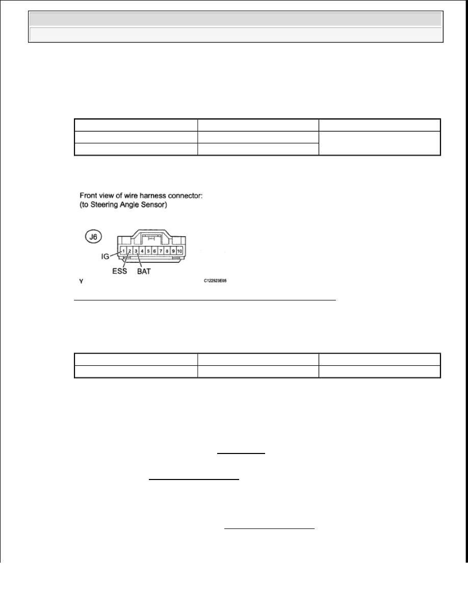
Fig. 57: Identifying J6 Steering Angle Sensor Connector Terminals
Courtesy of TOYOTA MOTOR SALES, U.S.A., INC.
Standard Resistance
TESTER CONNECTION SPECIFIED CONDITION TABLE
NG: REPAIR OR REPLACE HARNESS OR CONNECTOR
OK: Go To Next Step
7. REPLACE STEERING ANGLE SENSOR
a. Replace the steering angle sensor (See REMOVAL ).
8. RECONFIRM DTC
a. Clear the DTC (See DTC CHECK/CLEAR ).
b. Start the engine.
c. Drive the vehicle at a speed of 45 km/h (28 mph) or more and turn the steering wheel to the right
and left for several seconds.
d. Check if the same DTC is recorded (See DTC CHECK/CLEAR ).
Result
Tester Connection
Switch Condition
Specified Condition
J6-1 (IG) - Body ground
Ignition switch ON
11 to 14 V
J6-3 (BAT) - Body ground
Always
Tester Connection
Condition
Specified Condition
J6-2 (ESS) - Body ground
Always
Below 1 ohms
2009 Toyota Tundra
2009 BRAKES Brake Control - Tundra