Toyota Tundra. Manual - part 926
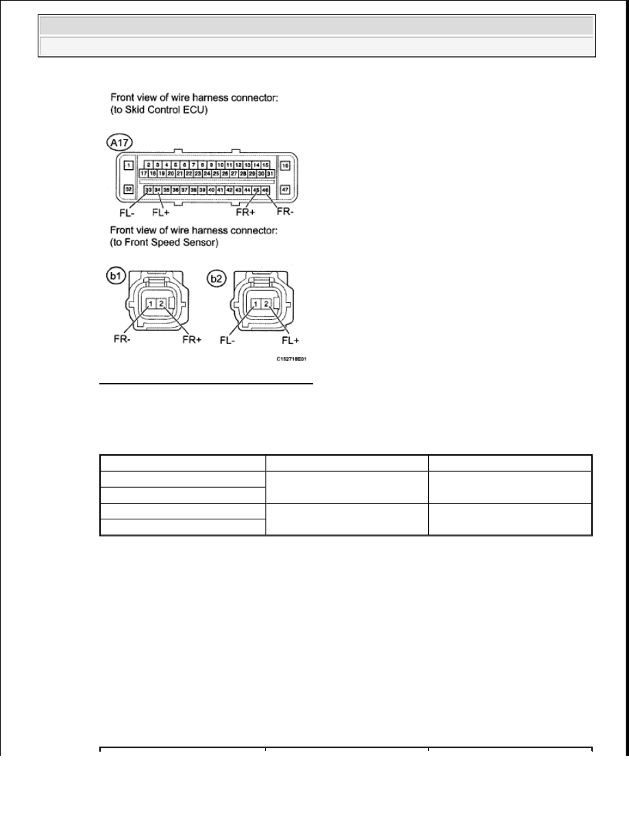
Fig. 38: Identifying A17 ECU Connector
Courtesy of TOYOTA MOTOR SALES, U.S.A., INC.
for LH
TESTER CONNECTION SPECIFIED CONDITION TABLE
NG: REPAIR OR REPLACE HARNESS OR CONNECTOR
OK: Go to next step
8. INSPECT FRONT SPEED SENSOR (INPUT VOLTAGE)
a. Reconnect the A17 ECU connector.
b. Disconnect the B1 and B2 sensor connectors.
c. Turn the ignition switch to ON.
d. Measure the voltage according to the value(s) in the table below.
Standard Voltage
TESTER CONNECTION SPECIFIED CONDITION TABLE
Tester Connection
Condition
Specified Condition
A17-34 (FL+) - B2-2 (FL+)
Always
Below 1 ohms
A17-33 (FL-) - B2-1 (FL-)
A17-34 (FL+) - Body ground
Always
10 kohms or higher
A17-33 (FL-) - Body ground
2009 Toyota Tundra
2009 BRAKES Brake Control - Tundra