Toyota Tundra. Manual - part 493
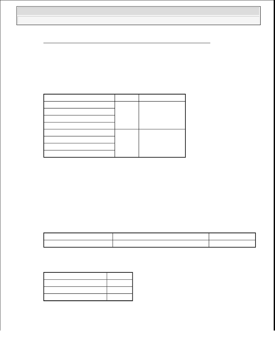
Fig. 100: Identifying K7 Receiver Connector And X1 Camera Connector
Courtesy of TOYOTA MOTOR SALES, U.S.A., INC.
b. Disconnect the X1 camera connector.
c. Measure the resistance according to the value(s) in the table below.
Standard resistance
NAVIGATION RECEIVER - TELEVISION CAMERA
NG: REPAIR OR REPLACE HARNESS OR CONNECTOR
OK: Go to next step
2. CHECK NAVIGATION RECEIVER (CA+ VOLTAGE)
a. Measure the voltage according to the value(s) in the table below.
Standard voltage
NAVIGATION RECEIVER (CA+ VOLTAGE) TESTER CONNECTION SPECIFIED
CONDITION
Result
NAVIGATION RECEIVER (CA+ VOLTAGE) RESULT CHART
Tester Connection
Condition Specified Condition
X1-3 (CB+) - K7-24 (CA+)
Always
Below 1 ohms
X1-4 (CGND) - K7-21 (CGND)
X1-1 (CV+) - K7-22 (V+)
X1-2 (CV-) - K7-23 (V-)
X1-3 (CB+) - Body ground
Always
10 kohms or higher
X1-4 (CGND) - Body ground
X1-1 (CV+) - Body ground
X1-2 (CV-) - Body ground
Tester Connection
Switch Condition
Specified Condition
K7-24 (CA+) - K7-21 (CGND) Ignition switch ON, shift lever in R position
5.5 to 7.05 V
Result
Proceed to
OK
A
NG (for Column Shift Type)
B
NG (for Floor Shift Type)
C
2009 Toyota Tundra
2009 ACCESSORIES AND EQUIPMENT Navigation - Tundra