Toyota Tundra. Manual - part 434
 

  Index      Toyota     Toyota Tundra (2007-2010 year) - Service and Repair Manual


Search            copyright infringement  


Content   ..  432  433  434  435   ..


Toyota Tundra. Manual - part 434


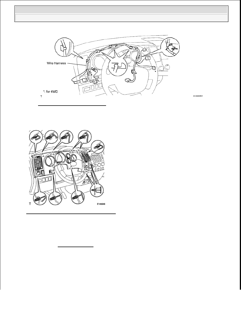
Fig. 68: Identifying Wire Harness 
Courtesy of TOYOTA MOTOR SALES, U.S.A., INC. 

c. Attach the 12 clips to install the finish panel.  

Fig. 69: Identifying Connectors And Clamps 
Courtesy of TOYOTA MOTOR SALES, U.S.A., INC. 

3. CONNECT CABLE TO NEGATIVE BATTERY TERMINAL 

ACCESSORY METER 

COMPONENTS 

NOTE:

Some systems need to be initialized after the cable is reconnected (see 
INITIALIZATION ).


2009 Toyota Tundra 

2009 ACCESSORIES AND EQUIPMENT Meter - Tundra


Fig. 70: Identifying Accessory Meter Components 
Courtesy of TOYOTA MOTOR SALES, U.S.A., INC. 

ON-VEHICLE INSPECTION 


2009 Toyota Tundra 

2009 ACCESSORIES AND EQUIPMENT Meter - Tundra


Fig. 71: Identifying Accessory Meter Assembly 
Courtesy of TOYOTA MOTOR SALES, U.S.A., INC. 

1. INSPECT ACCESSORY METER ASSEMBLY 

a. Measure the resistance according to the value(s) in the table below. 

Standard resistance  

ACCESSORY METER ASSEMBLY RESISTANCE REFERENCE 

b. Measure the voltage according to the value(s) in the table below. 

Standard voltage  

ACCESSORY METER ASSEMBLY VOLTAGE SPECIFICATIONS 

REMOVAL 

1. REMOVE INSTRUMENT PANEL SUB-ASSEMBLY 

a. for Column Shift Type: 

Remove the instrument panel (see REMOVAL ). 

b. for Floor Shift Type: 

Remove the instrument panel (see REMOVAL ). 

Tester Connection Condition Specified Condition

12 (E)-Body ground Always

Below 1 ohms

Tester Connection

Condition

Specified Condition

22 (ACC) - Body ground

Ignition switch OFF

Below 1 V

Ignition switch ACC

10 to 14 V

24 (+B) - Body ground

Always

10 to 14 V


2009 Toyota Tundra 

2009 ACCESSORIES AND EQUIPMENT Meter - Tundra


2. REMOVE NO. 1 HEATER TO REGISTER DUCT WITH NO. 2 HEATER TO REGISTER DUCT 

(See DISASSEMBLY )  

3. REMOVE NO. 2 SIDE DEFROSTER NOZZLE DUCT (See DISASSEMBLY )  

4. REMOVE NO. 3 INSTRUMENT PANEL REGISTER ASSEMBLY (See DISASSEMBLY )  

5. REMOVE NO. 1 SIDE DEFROSTER NOZZLE DUCT (See DISASSEMBLY )  

6. REMOVE DEFROSTER NOZZLE ASSEMBLY (See DISASSEMBLY )  

7. REMOVE ACCESSORY METER ASSEMBLY 

a. Disconnect the accessory meter connector. 

Fig. 72: Identifying Accessory Meter Connector 
Courtesy of TOYOTA MOTOR SALES, U.S.A., INC. 

b. Remove the 3 screws and accessory meter.  

INSTALLATION 

1. INSTALL ACCESSORY METER ASSEMBLY 

a. Install the accessory meter with the 3 screws. 

Fig. 73: Identifying Accessory Meter With Screws 
Courtesy of TOYOTA MOTOR SALES, U.S.A., INC. 

b. Connect the accessory meter connector.  

2. INSTALL DEFROSTER NOZZLE ASSEMBLY (See REASSEMBLY )  


2009 Toyota Tundra 

2009 ACCESSORIES AND EQUIPMENT Meter - Tundra


Content   ..  432  433  434  435   ..