Toyota Tundra. Manual - part 2693


  Index      Toyota     Toyota Tundra (2007-2010 year) - Service and Repair Manual


Search            copyright infringement  


Content   ..  2691  2692  2693  2694   ..


Toyota Tundra. Manual - part 2693


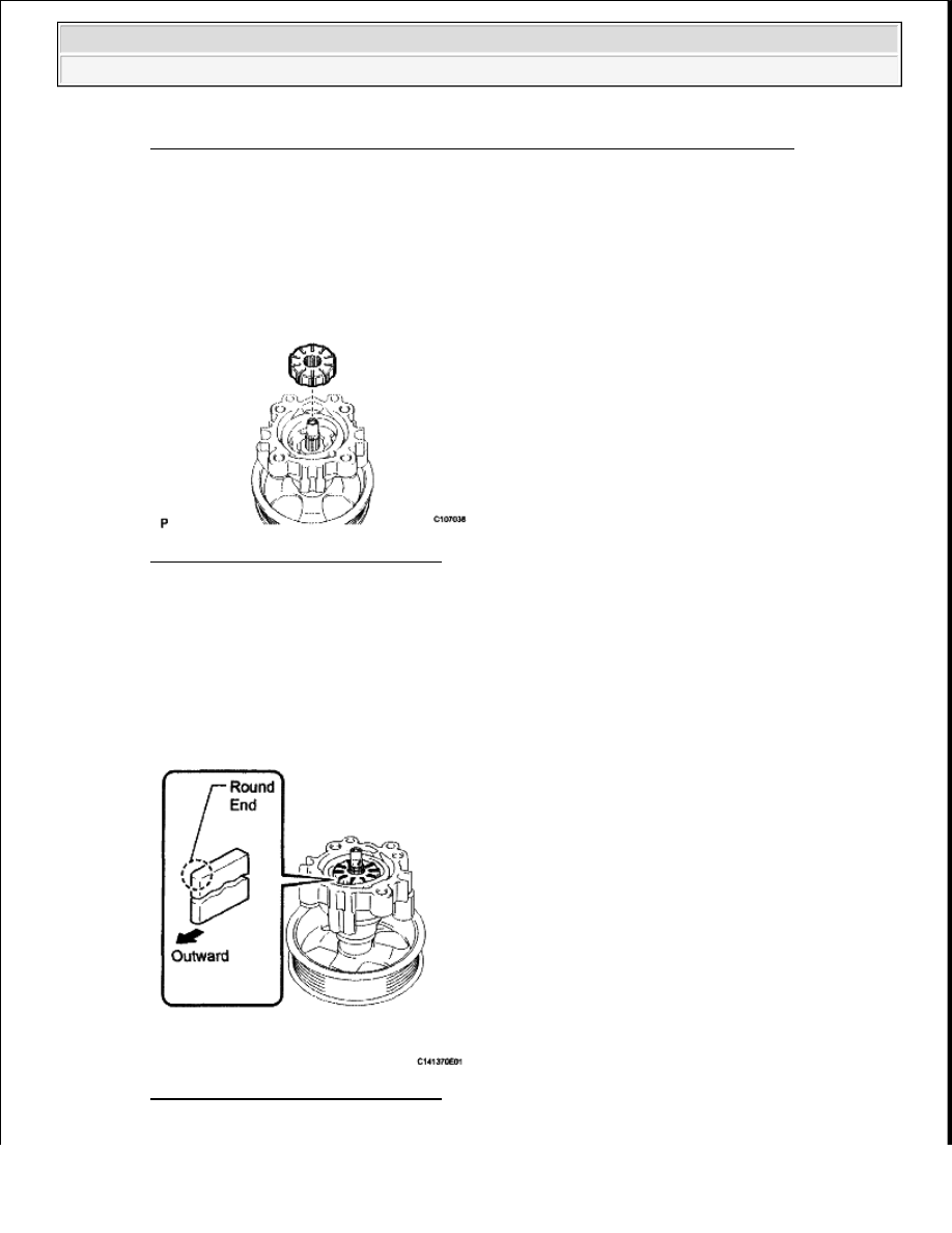
Fig. 93: Aligning Notch Of Cam Ring With That Of Vane Pump Front Side Plate 
Courtesy of TOYOTA MOTOR SALES, U.S.A., INC. 

5. INSTALL VANE PUMP ROTOR 

a. Install the vane pump rotor. 

Fig. 94: Installing Vane Pump Rotor 
Courtesy of TOYOTA MOTOR SALES, U.S.A., INC. 

HINT: 

The vane pump rotor can be installed in both directions. 

b. Coat the 10 vane pump plates with power steering fluid.  

c. Install the vane pump plates with the round end facing outward. 

Fig. 95: Installing Vane Pump Plates 
Courtesy of TOYOTA MOTOR SALES, U.S.A., INC. 

NOTE:

Make sure that the cam ring is installed facing in the correct 
direction.


2009 Toyota Tundra 

2009 STEERING Power Steering - Tundra


6. INSTALL VANE PUMP SHAFT SNAP RING 

a. Using a screwdriver and snap ring expander, install a new shaft snap ring onto the vane pump shaft. 

Fig. 96: Installing Vane Pump Shaft Snap Ring 
Courtesy of TOYOTA MOTOR SALES, U.S.A., INC. 

7. INSTALL VANE PUMP REAR HOUSING 

a. Coat a new O-ring with power steering fluid and install it onto the rear housing. 

Fig. 97: Identifying O-Ring On Pump Rear Housing 
Courtesy of TOYOTA MOTOR SALES, U.S.A., INC. 

b. Align the straight pin of the rear housing with the notches of the cam ring, front side plate, and 

front housing. 

NOTE:

Make sure that the vane pump plates are installed facing in the 
correct direction.


2009 Toyota Tundra 

2009 STEERING Power Steering - Tundra


Fig. 98: Aligning Straight Pin Of Vane Pump Rear Housing 
Courtesy of TOYOTA MOTOR SALES, U.S.A., INC. 

c. Install the rear housing with the 4 bolts. 

Fig. 99: Identifying Vane Pump Rear Housing Bolts 
Courtesy of TOYOTA MOTOR SALES, U.S.A., INC. 

Torque: 22 N*m (224 kgf*cm, 16 ft.*lbf)  

8. INSPECT TOTAL PRELOAD (see INSPECTION )  

9. INSTALL FLOW CONTROL VALVE ASSEMBLY 

a. Coat the flow control valve with power steering fluid.  

b. Install the compression spring and flow control valve to the front housing.  

c. Coat a new O-ring with power steering fluid and install it onto the pressure port union. 


2009 Toyota Tundra 

2009 STEERING Power Steering - Tundra


Fig. 100: Identifying Flow Control Valve O-Ring And Compression Spring 
Courtesy of TOYOTA MOTOR SALES, U.S.A., INC. 

d. Install the pressure port union to the front housing. 

Torque: 69 N*m (704 kgf*cm, 51 ft.*lbf)  

10. INSTALL POWER STEERING SUCTION PORT UNION 

a. Coat a new O-ring with power steering fluid and install it to the suction port union.  

b. Install the suction port union to the vane pump with the bolt. 

Torque: 12 N*m (122 kgf*cm, 9 ft.*lbf)  

INSTALLATION 

1. INSTALL VANE PUMP ASSEMBLY 

a. Install the 2 bolts and nut. 

Fig. 101: Identifying Power Steering Suction Port Union Bolt 
Courtesy of TOYOTA MOTOR SALES, U.S.A., INC. 

Torque: 28 N*m (286 kgf*cm, 21 ft.*lbf)  

2. CONNECT PRESSURE FEED TUBE 

a. Connect the pressure feed tube. 


2009 Toyota Tundra 

2009 STEERING Power Steering - Tundra


Content   ..  2691  2692  2693  2694   ..