Toyota Tundra. Manual - part 2158


  Index      Toyota     Toyota Tundra (2007-2010 year) - Service and Repair Manual


Search            copyright infringement  


Content   ..  2156  2157  2158  2159   ..


Toyota Tundra. Manual - part 2158


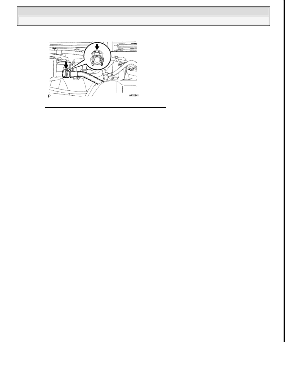
Fig. 117: Identifying Vent Line Hose And Retainer 
Courtesy of TOYOTA MOTOR SALES, U.S.A., INC. 

10. CONNECT FUEL TANK RETURN TUBE 

a. Connect the fuel tank return tube. 

HINT: 

Push the parts together firmly until a "click" sound is heard. 

b. Attach the lock claws to the connector by pushing down on the cover, as shown in the illustration. 

NOTE:

Before installing the hose, make sure that it is not damaged. 
Make sure that there is no foreign matter present on the 
connecting surfaces.  

After connecting, check if the hose and the connector are 
securely connected by pulling on them.  

NOTE:

Before installing the tube connectors to the pipes, check if there 
is any damage or foreign matter in the connectors.  

After the connection, check if the connectors and pipes are 
securely connected by trying to pull them apart.  


2009 Toyota Tundra 

2009 ENGINE Fuel (3UR-FE) - Tundra


Fig. 118: Attaching Lock Claws To Connector By Pushing Down On Cover 
Courtesy of TOYOTA MOTOR SALES, U.S.A., INC. 

11. CONNECT FUEL TANK MAIN TUBE SUB-ASSEMBLY 

a. Connect the fuel tank main tube. 

HINT: 

Push the parts together firmly until a "click" sound is heard. 

b. Attach the lock claws to the connector by pushing down on the cover, as shown in the illustration. 

NOTE:

Before installing the tube connectors to the pipes, check if there 
is any damage or foreign matter in the connectors.  

After the connection, check if the connectors and pipes are 
securely connected by trying to pull them apart.  


2009 Toyota Tundra 

2009 ENGINE Fuel (3UR-FE) - Tundra


Fig. 119: Attaching Lock Claws To Connector By Pushing Down On Cover 
Courtesy of TOYOTA MOTOR SALES, U.S.A., INC. 

12. INSTALL NO. 1 FUEL TANK PROTECTOR SUB-ASSEMBLY (for Rough Road Area 

Specification Vehicles) 

a. Install the tank protector with the 2 bolts and 2 nuts. 

Torque: for bolt 29 N*m (296 kgf*cm, 21 ft.*lbf) for nut 20 N*m (204 kgf*cm, 15 ft.*lbf)  

13. INSTALL FUEL TANK CAP  

14. CONNECT CABLE TO NEGATIVE BATTERY TERMINAL 

15. INSPECT FOR FUEL LEAK (see INSTALLATION )  

FUEL SENDER GAUGE ASSEMBLY 

COMPONENTS 

NOTE:

Some systems need to be initialized after the cable is reconnected (see 
INITIALIZATION ).


2009 Toyota Tundra 

2009 ENGINE Fuel (3UR-FE) - Tundra


Fig. 120: Identifying Fuel Sender Gauge Assembly Components With Torque Specifications (1 Of 4) 
Courtesy of TOYOTA MOTOR SALES, U.S.A., INC. 


2009 Toyota Tundra 

2009 ENGINE Fuel (3UR-FE) - Tundra


Content   ..  2156  2157  2158  2159   ..