Toyota Tundra. Manual - part 1993


  Index      Toyota     Toyota Tundra (2007-2010 year) - Service and Repair Manual


Search            copyright infringement  


Content   ..  1991  1992  1993  1994   ..


Toyota Tundra. Manual - part 1993


a

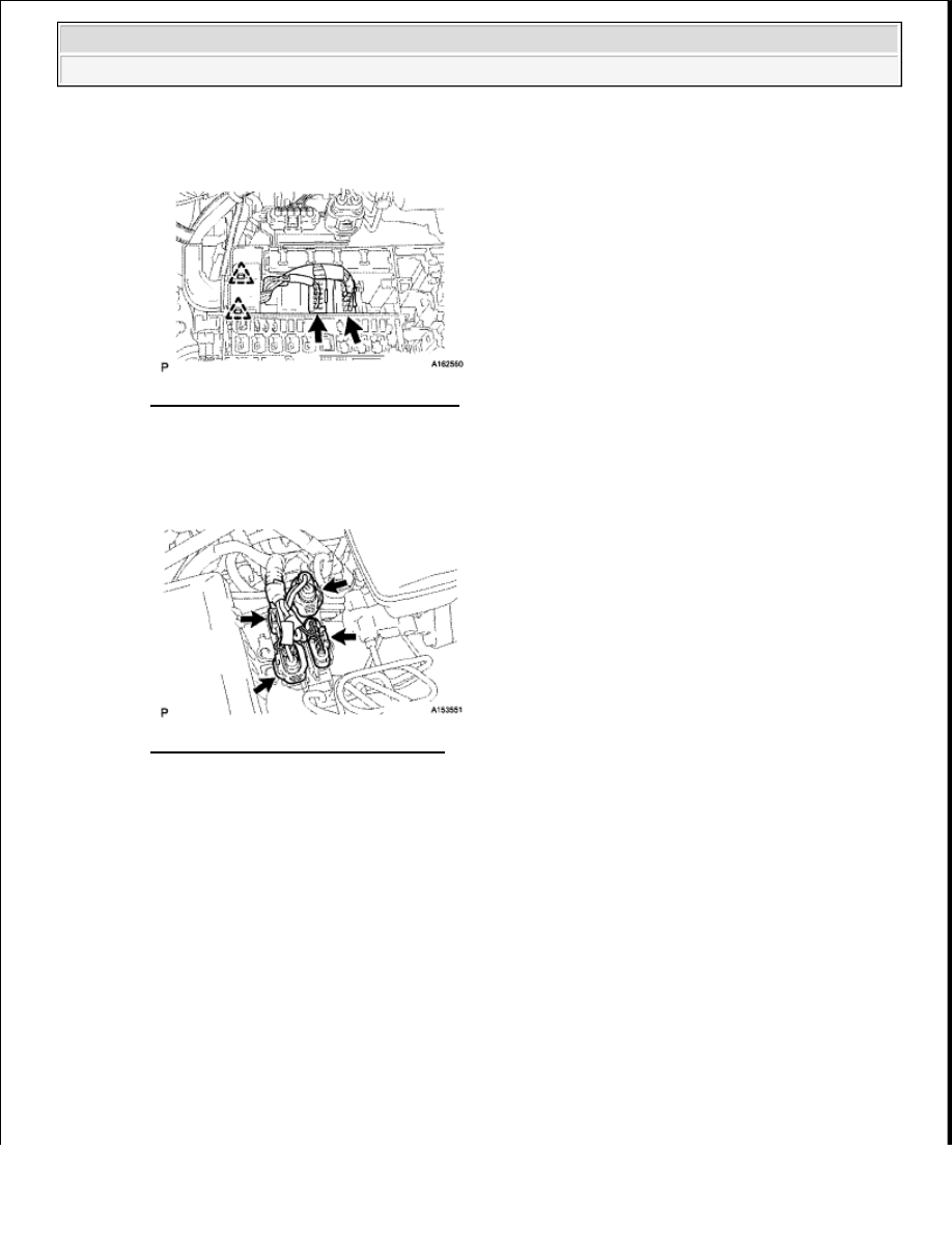
Using needle-nose pliers, remove the oil seals  

Fig. 36: Removing Valve Stem Oil Seal 
Courtesy of TOYOTA MOTOR SALES, U.S.A., INC. 

4

REMOVE VALVE SPRING SEAT 

a

Using compressed air and a magnetic finger, remove the valve spring seat by blowing air onto it  

Fig. 37: Removing Valve Spring Seat 
Courtesy of TOYOTA MOTOR SALES, U.S.A., INC. 

5

REMOVE NO. 1 STRAIGHT SCREW PLUG 

a

Using a 10 mm hexagon wrench, remove the 6 screw plugs and 6 gaskets  

NOTE:

If water leaks from the No. 1 screw plug or the plug is corroded, replace it.


2009 Toyota Tundra 

2009 ENGINE Engine Mechanical (3UR-FE) - Tundra


Fig. 38: Locating No. 1 Screw Plugs And Gaskets 
Courtesy of TOYOTA MOTOR SALES, U.S.A., INC. 

6

REMOVE NO. 2 STRAIGHT SCREW PLUG 

a

Using a 14 mm hexagon wrench, remove the 2 screw plugs and 2 gaskets  

Fig. 39: Locating No. 2 Screw Plug And Gaskets 
Courtesy of TOYOTA MOTOR SALES, U.S.A., INC. 

7

REMOVE STUD BOLT 

INSPECTION 

1

INSPECT CAMSHAFT OIL CLEARANCE 

a

Clean the bearing caps, camshaft housing and camshaft journals   

b

Place the camshafts on the camshaft housing   

c

Lay a strip of Plastigage across each of the camshaft journals  

NOTE:

If water leaks from the No. 2 screw plug or the plug is corroded, 
replace it.

NOTE:

If the stud bolt is deformed or its threads are damaged, replace it.


2009 Toyota Tundra 

2009 ENGINE Engine Mechanical (3UR-FE) - Tundra


Fig. 40: Laying Strip Of Plastigage Across Camshaft Journals 
Courtesy of TOYOTA MOTOR SALES, U.S.A., INC. 

d

Install the camshaft bearing caps (see REASSEMBLY )  

e

Install the camshaft housing (see REASSEMBLY )  

f

Remove the camshaft bearing caps (see DISASSEMBLY )   

g

Measure the Plastigage at its widest point  

Standard oil clearance  

STANDARD OIL CLEARANCE SPECIFICATIONS 

Maximum oil clearance  

MAXIMUM OIL CLEARANCE SPECIFICATIONS 

NOTE:

Do not turn the camshaft.

NOTE:

Do not turn the camshaft.

Item

Specified Condition

No  1 journal 0 030 to 0 065 mm (0 00118 to 0 00256 in )

Other journals 0 025 to 0 062 mm (0 000984 to 0 00244 in )

Item

Specified Condition


2009 Toyota Tundra 

2009 ENGINE Engine Mechanical (3UR-FE) - Tundra


Fig. 41: Measuring Plastigage At Widest Point 
Courtesy of TOYOTA MOTOR SALES, U.S.A., INC. 

If the oil clearance is greater than the maximum, replace the camshaft  If necessary, replace the 
camshaft housing  

2

INSPECT CAMSHAFT THRUST CLEARANCE 

a

Inspect the LH side camshafts  

1

Install the LH side camshafts   

2

Using a dial indicator, measure the thrust clearance while moving the camshaft back and 
forth  

Standard thrust clearance: 0.08 to 0.135 mm (0.00315 to 0.00531 in.)  

Maximum thrust clearance: 0.15 mm (0.00591 in.)  

If the thrust clearance is greater than the maximum, replace the camshaft housing  If the 
thrust surface is damaged, replace the camshaft  

No  1 journal 0 10 mm (0 00394 in )

Other journals 0 09 mm (0 00354 In )


2009 Toyota Tundra 

2009 ENGINE Engine Mechanical (3UR-FE) - Tundra


Content   ..  1991  1992  1993  1994   ..