Toyota Tundra. Manual - part 1860


  Index      Toyota     Toyota Tundra (2007-2010 year) - Service and Repair Manual


Search            copyright infringement  


Content   ..  1858  1859  1860  1861   ..


Toyota Tundra. Manual - part 1860
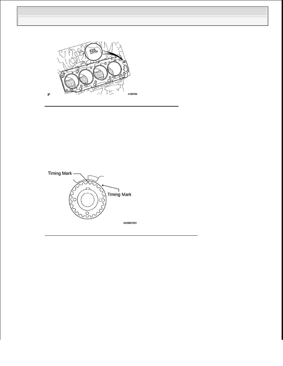


Fig. 103: Identifying Cylinder Block And Cylinder Head 
Courtesy of TOYOTA MOTOR SALES, U.S.A., INC. 

4

INSTALL CYLINDER HEAD LH 

a

Check that the timing mark of the crankshaft timing pulley is in the position shown below, and that 
the piston is below the TDC of compression   

b

Install the cylinder head with the exhaust manifold to the cylinder block  

Fig. 104: Identifying Timing Mark Of Crankshaft Timing Pulley 
Courtesy of TOYOTA MOTOR SALES, U.S.A., INC. 

c

Apply a light coat of engine oil to the threads and under the heads of the cylinder head bolts   

d

Step 1: 

1

Set the plate washer to the cylinder head bolt   

2

Install and uniformly tighten the 10 cylinder head bolts and plate washers in the sequence 
shown below  

Torque: 32 N*m (326 kgf*cm, 24 ft.*lbf)  

If any one of the cylinder head bolts does not meet the torque specification, replace the 
cylinder head bolt  

NOTE:

Ensure that no oil is on the mounting surface of the cylinder head.


2009 Toyota Tundra 

2009 ENGINE Engine Mechanical (2UZ-FE) - Tundra


Fig. 105: Identifying Cylinder Head Bolt Tightening Sequence 
Courtesy of TOYOTA MOTOR SALES, U.S.A., INC. 

HINT: 

The cylinder head bolts are tightened in 3 progressive steps  

e

Step 2: 

1

Mark the cylinder head bolt head with paint as shown below   

2

Tighten the cylinder head bolts another 90° in the sequence shown below  

Fig. 106: Identifying Cylinder Head Bolt Paint Mark 
Courtesy of TOYOTA MOTOR SALES, U.S.A., INC. 

f

Step 3: 

1

Tighten the cylinder head bolts another 90° in the sequence shown in step 1   

2

Check that the painted marks are now facing rearward   

5

INSTALL VALVE LIFTER 

a

Apply a light coat of engine oil to the valve lifters and shims   

b

Install the valve lifters and shims to the cylinder head   

c

Check that the valve lifter rotates smoothly by hand   

NOTE:

Do not drop the plate washer for the cylinder head bolt into 
portion A of the cylinder head. If dropped into portion A, the 
plate washer will pass through the cylinder head and cylinder 
block into the oil pan.


2009 Toyota Tundra 

2009 ENGINE Engine Mechanical (2UZ-FE) - Tundra


6

INSTALL CAMSHAFT SETTING OIL SEAL (See REASSEMBLY )  

7

INSTALL CAMSHAFT TIMING TUBE ASSEMBLY (See REASSEMBLY )  

8

INSTALL CAMSHAFT SUB-ASSEMBLY LH 

a

Apply a light coat of engine oil to the cam lobe and gear of the camshaft and also the journal of the 
cylinder head  

Fig. 107: Identifying Crankshaft Pulley Angle 
Courtesy of TOYOTA MOTOR SALES, U.S.A., INC. 

b

Using a wrench, align the timing marks (2 dot marks each) of the camshaft drive and driven main 
gears, and set the No  3 and No  4 camshafts in place   

c

Install the bearing cap  

Fig. 108: Aligning Timing Marks (2 Dot Marks Each) Of Camshaft Drive And Driven Main 
Gears
 

NOTE:

As the thrust clearance of the camshaft is small, the camshaft must 
be kept level while it is being removed. If the camshaft is not kept 
level, the portion of the cylinder head which receives the shaft thrust 
may crack or be damaged. To avoid this, the following steps should 
be carried out.  

Having the crankshaft pulley at a wrong angle can cause the piston 
head and valve head to come into contact with each other when 
removing the camshaft. Always set the crankshaft pulley at the 
correct angle as shown below.  


2009 Toyota Tundra 

2009 ENGINE Engine Mechanical (2UZ-FE) - Tundra


Courtesy of TOYOTA MOTOR SALES, U.S.A., INC. 

1

Apply seal packing to the camshaft housing plug groove  

HINT: 

Remove any old packing (FIPG) material before applying new seal packing  

Seal packing: Toyota Genuine Seal Packing Black, Three Bond 1207B or equivalent  

Fig. 109: Identifying Seal Packing Applying Location 
Courtesy of TOYOTA MOTOR SALES, U.S.A., INC. 

2

Install the camshaft housing plug and oil control valve filter to the cylinder head as shown 
below  

3

Apply seal packing to the No  1 bearing cap as shown below  

NOTE:

Be careful of the installation direction.  

Remove any oil from the contact surface. 

Fig. 110: Identifying Oil Control Valve Filter And Camshafts 
Courtesy of TOYOTA MOTOR SALES, U.S.A., INC. 


2009 Toyota Tundra 

2009 ENGINE Engine Mechanical (2UZ-FE) - Tundra


Content   ..  1858  1859  1860  1861   ..