Toyota Tundra. Manual - part 1563


  Index      Toyota     Toyota Tundra (2007-2010 year) - Service and Repair Manual


Search            copyright infringement  


Content   ..  1561  1562  1563  1564   ..


Toyota Tundra. Manual - part 1563


NG: REPAIR OR REPLACE HARNESS OR CONNECTOR  

OK: Go to Next Step  

2. CHECK HARNESS AND CONNECTOR (IGNITION COIL ASSEMBLY - ECM) 

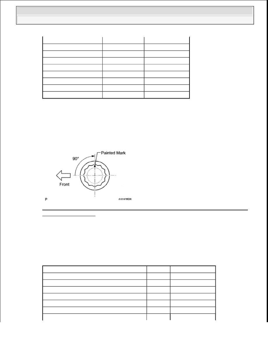
a. Disconnect the D10, D12, D14, D16, D19, D21, D23 or D25 ignition coil with igniter connector. 

Fig. 151: Identifying Terminals Of D10, D12, D14, D16, D19, D21, D23 Or D25 Ignition Coil 
With Igniter Connector
 
Courtesy of TOYOTA MOTOR SALES, U.S.A., INC. 

b. Disconnect the D74 ECM connector.  

c. Measure the resistance according to the value(s) in the table below. 

Standard resistance  

RESISTANCE SPECIFIED CONDITION 

Tester Connection

Switch Condition Specified Condition

D10-1 (+B) - D10-4 (GND) Ignition switch ON

11 to 14 V

D25-1 (+B) - D25-4 (GND) Ignition switch ON

11 to 14 V

D12-1 (+B) - D12-4 (GND) Ignition switch ON

11 to 14 V

D23-1 (+B) - D23-4 (GND) Ignition switch ON

11 to 14 V

D14-1 (+B) - D14-4 (GND) Ignition switch ON

11 to 14 V

D21-1 (+B) - D21-4 (GND) Ignition switch ON

11 to 14 V

D16-1 (+B) - D16-4 (GND) Ignition switch ON

11 to 14 V

D19-1 (+B) - D19-4 (GND) Ignition switch ON

11 to 14 V

Tester Connection

Condition Specified Condition

D10-2 (IGF1) - D74-104 (IGF1)

Always

Below 1 ohms

D25-2 (IGF2) - D74-105 (IGF2)

Always

Below 1 ohms

D12-2 (IGF2) - D74-105 (IGF2)

Always

Below 1 ohms

D23-2 (IGF1) - D74-104 (IGF1)

Always

Below 1 ohms

D14-2 (IGF2) - D74-105 (IGF2)

Always

Below 1 ohms

D21-2 (IGF1) - D74-104 (IGF1)

Always

Below 1 ohms


2009 Toyota Tundra 

2009 ENGINE PERFORMANCE Engine Control System (3UR-FBE) - Tundra


NG: REPAIR OR REPLACE HARNESS OR CONNECTOR  

OK: Go to Next Step  

3. CHECK WHETHER DTC OUTPUT RECURS (DTC P0351, P0352, P0353, P0354, P0355, P0356, 

P0357 OR P0358) 

a. Connect the Techstream to the DLC3.  

b. Turn the ignition switch to ON and turn the Techstream ON.  

c. Clear DTCs (see DTC CHECK/CLEAR ).  

d. Shuffle the arrangement of the ignition coils with igniters (among No. 1 to No. 8 cylinders). 

e. Perform a simulation test.  

f. Check DTCs displayed on the Techstream. 

D16-2 (IGF1) - D74-104 (IGF1)

Always

Below 1 ohms

D19-2 (IGF2) - D74-105 (IGF2)

Always

Below 1 ohms

D10-3 (IGT1) - D74-40 (IGT1)

Always

Below 1 ohms

D25-3 (IGT2) - D74-33 (IGT2)

Always

Below 1 ohms

D12-3 (IGT3) - D74-37 (IGT3)

Always

Below 1 ohms

D23-3 (IGT4) - D74-34 (IGT4)

Always

Below 1 ohms

D14-3 (IGT5) - D74-35 (IGT5)

Always

Below 1 ohms

D21-3 (IGT6) - D74-36 (IGT6)

Always

Below 1 ohms

D16-3 (IGT7) - D74-38 (IGT7)

Always

Below 1 ohms

D19-3 (IGT8) - D74-39 (IGT8)

Always

Below 1 ohms

D10-2 (IGF1) or D74-104 (IGF1) - Body ground Always

10 kohms or higher

D25-2 (IGF2) or D74-105 (IGF2) - Body ground Always

10 kohms or higher

D12-2 (IGF2) or D74-105 (IGF2) - Body ground Always

10 kohms or higher

D23-2 (IGF1) or D74-104 (IGF1) - Body ground Always

10 kohms or higher

D14-2 (IGF2) or D74-105 (IGF2) - Body ground Always

10 kohms or higher

D21-2 (IGF1) or D74-104 (IGF1) - Body ground Always

10 kohms or higher

D16-2 (IGF1) or D74-104 (IGF1) - Body ground Always

10 kohms or higher

D19-2 (IGF2) or D74-105 (IGF2) - Body ground Always

10 kohms or higher

D10-3 (IGT1) or D74-40 (IGT1) - Body ground

Always

10 kohms or higher

D25-3 (IGT2) or D74-33 (IGT2) - Body ground

Always

10 kohms or higher

D12-3 (IGT3) or D74-37 (IGT3) - Body ground

Always

10 kohms or higher

D23-3 (IGT4) or D74-34 (IGT4) - Body ground

Always

10 kohms or higher

D14-3 (IGT5) or D74-35 (IGT5) - Body ground

Always

10 kohms or higher

D21-3 (IGT6) or D74-36 (IGT6) - Body ground

Always

10 kohms or higher

D16-3 (IGT7) or D74-38 (IGT7) - Body ground

Always

10 kohms or higher

D19-3 (IGT8) or D74-39 (IGT8) - Body ground

Always

10 kohms or higher

NOTE:

Do not shuffle the connectors.


2009 Toyota Tundra 

2009 ENGINE PERFORMANCE Engine Control System (3UR-FBE) - Tundra


Result  

RESULT REFERENCE 

B: REPLACE IGNITION COIL ASSEMBLY (See REMOVAL ) 

A: REPLACE ECM (See REMOVAL ) 

DTC P0365 CAMSHAFT POSITION SENSOR "B" CIRCUIT (BANK 1); DTC P0367 CAMSHAFT 
POSITION SENSOR "B" CIRCUIT LOW INPUT (BANK 1); DTC P0368 CAMSHAFT POSITION 
SENSOR "B" CIRCUIT HIGH INPUT (BANK 1); DTC P0390 CAMSHAFT POSITION SENSOR "B" 
CIRCUIT (BANK 2); DTC P0392 CAMSHAFT POSITION SENSOR "B" CIRCUIT LOW INPUT 
(BANK 2); DTC P0393 CAMSHAFT POSITION SENSOR "B" CIRCUIT HIGH INPUT (BANK 2) 

DESCRIPTION 

The exhaust camshaft's Variable Valve Timing (VVT) sensor (EV1, 2 signal) consists of a magnet and MRE 
(Magnetic Resistance Element). 

The exhaust camshaft has 3 teeth on its outer circumference. When the exhaust camshaft rotates, changes occur 
in the air gaps between the teeth and MRE, which affects the magnetic field. As a result, the resistance of the 
MRE material fluctuates. The VVT sensor converts the exhaust camshaft rotation data into pulse signals, uses 
the pulse signals to determine the camshaft angle, and sends it to the ECM. 

DTC DETECTION CONDITION AND TROUBLE AREA REFERENCE CHART 

Result

Proceed to

Same DTC is output

A

Different ignition coil DTC is output

B

DTC

DTC Detection Condition

Trouble Area

P0365 
P0390

No VVT sensor signal to ECM 
during engine running (1 trip 
detection logic)

Open or short in VVT sensor 
for exhaust camshaft circuit  

VVT sensor for exhaust 
camshaft  

Exhaust camshaft  

Jumped tooth of timing chain 

ECM  

P0367 
P0392

Output voltage of VVT sensor less 
than 0.3 V 4 seconds (1 trip 
detection logic)

Open or short in VVT sensor 
for exhaust camshaft circuit  

VVT sensor for exhaust 
camshaft  

Exhaust camshaft  

Jumped tooth of timing chain 

ECM  


2009 Toyota Tundra 

2009 ENGINE PERFORMANCE Engine Control System (3UR-FBE) - Tundra


Reference: Inspection using an oscilloscope 

Fig. 152: Identifying EV1, EV2 And NE Signal Waveform 
Courtesy of TOYOTA MOTOR SALES, U.S.A., INC. 

Standard  

WAVEFORM REFERENCE 

HINT: 

EV1+ and EV2+ stand for the VVT sensor signal, and NE+ stands for the CKP sensor signal. 

MONITOR DESCRIPTION 

If no signal is transmitted by the VVT sensor despite the engine revolving, or the rotations of the camshaft and 
the crankshaft are not synchronized, the ECM interprets this as a malfunction of the sensor. 

MONITOR STRATEGY 

P0368 
P0393

Output voltage of VVT sensor 
more than 4.7 V 4 seconds (1 trip 
detection logic)

Open or short in VVT sensor 
for exhaust camshaft circuit  

VVT sensor for exhaust 
camshaft  

Exhaust camshaft  

Jumped tooth of timing chain 

ECM  

Tester Connection

Tool Setting

Condition

Specified Condition

D74-110 (NE+) - D74-111 (NE-)

5 V/DIV. 
20 msec./DIV.

Cranking or Idling The correct waveform is as shown

D74-69 (EV1+) - D74-68 (EV1-)

5 V/DIV. 
20 msec./DIV.

Cranking or Idling The correct waveform is as shown

D74-64 (EV2+) - D74-65 (EV2-)

5 V/DIV. 
20 msec./DIV.

Cranking or Idling The correct waveform Is as shown


2009 Toyota Tundra 

2009 ENGINE PERFORMANCE Engine Control System (3UR-FBE) - Tundra


Content   ..  1561  1562  1563  1564   ..