Content .. 1562 1563 1564 1565 ..
Toyota Tundra. Manual - part 1564
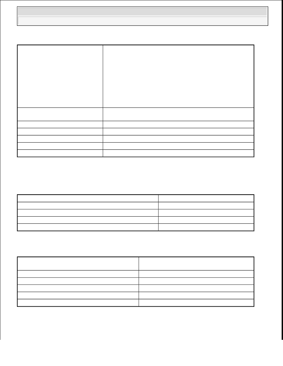
MONITOR STRATEGY
TYPICAL ENABLING CONDITIONS
P0367, P0368, P0392, P0393
TYPICAL ENABLING CONDITIONS - P0367, P0368, P0392, P0393
P0365, P0390
TYPICAL ENABLING CONDITIONS - P0365, P0390
TYPICAL MALFUNCTION THRESHOLDS
P0367, P0392:
Related DTCs
P0365: VVT sensor (for Bank 1) verify pulse input
P0367: VVT position sensor (for Bank 1) range check (low
voltage)
P0368: VVT position sensor (for Bank 1) range check (high
voltage)
P0390: VVT sensor (for Bank 2) verify pulse input
P0392: VVT position sensor (for Bank 2) range check (low
voltage)
P0393: VVT position sensor (for Bank 2) range check (high
voltage)
Required Sensors/Components
(Main)
VVT position sensor (for Bank 1 and 2)
Required Sensors/Components (Sub) Crankshaft position sensor
Frequency of Operation
Continuous
Duration
5 seconds
MIL Operation
Immediate
Sequence of Operation
None
Monitor runs whenever following DTCs are not present
P0365, P0390 (Exhaust VVT Sensor)
Starter
OFF
Ignition switch
ON
Time after ignition switch off to ON
2 seconds or more
Battery voltage
8 V or more
Monitor runs whenever following DTCs are not
present
P0367, P0368, P0392, P0393 (Exhaust VVT
Sensor)
Exhaust VVT sensor voltage
0.3 to 4.7 V
Engine speed
600 RPM or more
Battery voltage
8 V or more
Starter
OFF
Ignition switch
ON
2009 Toyota Tundra
2009 ENGINE PERFORMANCE Engine Control System (3UR-FBE) - Tundra