Toyota Tundra. Manual - part 1561


  Index      Toyota     Toyota Tundra (2007-2010 year) - Service and Repair Manual


Search            copyright infringement  


Content   ..  1559  1560  1561  1562   ..


Toyota Tundra. Manual - part 1561
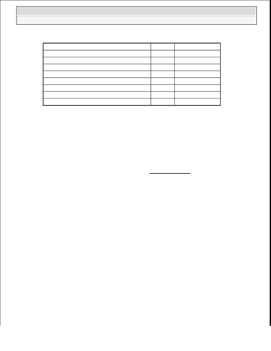


RESISTANCE SPECIFIED CONDITION 

NG: REPAIR OR REPLACE HARNESS OR CONNECTOR  

OK: Go to Next Step  

3. CHECK SENSOR INSTALLATION (VVT SENSOR FOR INTAKE CAMSHAFT) 

a. Check the VVT sensor installation. 

OK: Sensor is installed correctly.  

NG: SECURELY REINSTALL SENSOR (See INSTALLATION ) 

Tester Connection

Condition Specified Condition

D37-1 (VVL+) - D74-92 (VV1+)

Always

Below 1 ohms

D37-2 (VVL-) - D74-91 (VV1-)

Always

Below 1 ohms

D39-1 (VVR+) - D74-87 (VV2+)

Always

Below 1 ohms

D39-2 (VVR-) - D74-88 (VV2-)

Always

Below 1 ohms

D37-1 (VVL+) or D74-92 (VV1+) - Body ground Always

10 kohms or higher

D37-2 (VVL-) or D74-91 (VV1-) - Body ground

Always

10 kohms or higher

D39-1 (VVR+) or D74-87 (VV2+) - Body ground Always

10 kohms or higher

D39-2 (VVR-) or D74-88 (VV2-) - Body ground

Always

10 kohms or higher


2009 Toyota Tundra 

2009 ENGINE PERFORMANCE Engine Control System (3UR-FBE) - Tundra


Fig. 144: Checking VVT Sensor Installation 
Courtesy of TOYOTA MOTOR SALES, U.S.A., INC. 

OK: Go to Next Step  

4. CHECK INTAKE CAMSHAFT (TEETH) 

a. Check the teeth of the camshaft. 

OK: Teeth do not have any cracks or deformation.  


2009 Toyota Tundra 

2009 ENGINE PERFORMANCE Engine Control System (3UR-FBE) - Tundra


NG: REPLACE INTAKE CAMSHAFT (See DISASSEMBLY ) 

OK: Go to Next Step  

5. REPLACE VVT SENSOR 

a. Replace the VVT sensor (see INSTALLATION ).  

6. CHECK WHETHER DTC OUTPUT RECURS 

a. Connect the Techstream to the DLC3.  

b. Turn the ignition switch to ON.  

c. Turn the Techstream ON.  

d. Clear DTCs (see DTC CHECK/CLEAR ).  

e. Start the engine.  

f. Enter the following menus: Powertrain/Engine and ECT/Trouble Codes/Pending.  

g. Read DTCs. 

Result  

RESULT REFERENCE 

HINT: 

If the engine does not start, replace the ECM. 

B: REPLACE ECM (See REMOVAL ) 

A: END  

DTC P0351 IGNITION COIL "A" PRIMARY/SECONDARY CIRCUIT; DTC P0352 IGNITION COIL 
"B" PRIMARY/SECONDARY CIRCUIT; DTC P0353 IGNITION COIL "C" 
PRIMARY/SECONDARY CIRCUIT; DTC P0354 IGNITION COIL "D" PRIMARY/SECONDARY 
CIRCUIT; DTC P0355 IGNITION COIL "E" PRIMARY/SECONDARY CIRCUIT; DTC P0356 
IGNITION COIL "F" PRIMARY/SECONDARY CIRCUIT; DTC P0357 IGNITION COIL "G" 
PRIMARY/SECONDARY CIRCUIT; DTC P0358 IGNITION COIL "H" PRIMARY/SECONDARY 
CIRCUIT 

DESCRIPTION 

HINT: 

These DTCs indicate malfunctions relating to the primary circuit.  

If DTC P0351 is set, check the No. 1 ignition coil with igniter circuit.  

Display (DTC Output)

Proceed to

No output

A

P0340, P0342, P0343, P0345, P0347 or P0348

B


2009 Toyota Tundra 

2009 ENGINE PERFORMANCE Engine Control System (3UR-FBE) - Tundra


If DTC P0352 is set, check the No. 2 ignition coil with igniter circuit.  

If DTC P0353 is set, check the No. 3 ignition coil with igniter circuit.  

If DTC P0354 is set, check the No. 4 ignition coil with igniter circuit.  

If DTC P0355 is set, check the No. 5 ignition coil with igniter circuit.  

If DTC P0356 is set, check the No. 6 ignition coil with igniter circuit.  

If DTC P0357 is set, check the No. 7 ignition coil with igniter circuit.  

If DTC P0358 is set, check the No. 8 ignition coil with igniter circuit.  

A Direct Ignition System (DIS) is used on this vehicle. 

The DIS is a 1-cylinder ignition system in which each cylinder is ignited by one ignition coil and one spark plug 
is connected to the end of each secondary wiring. A powerful voltage, generated in the secondary wiring, is 
applied directly to each spark plug. The sparks of the spark plugs pass from the center electrode to the ground 
electrodes. 

The ECM determines the ignition timing and transmits the ignition (IGT) signals to each cylinder. Using the 
IGT signal, the ECM turns the power transistor inside the igniter on and off. The power transistor, in turn, 
switches on and off the current to the primary coil. When the current to the primary coil is cut off, a powerful 
voltage is generated in the secondary coil. This voltage is applied to the spark plugs, causing them to spark 
inside the cylinders. As the ECM cuts the current to the primary coil, the igniter sends back an ignition 
confirmation (IGF) signal to the ECM for each cylinder ignition. 

Fig. 145: Ignition Coil - Wiring Diagram 
Courtesy of TOYOTA MOTOR SALES, U.S.A., INC. 

DTC DETECTION CONDITION AND TROUBLE AREA REFERENCE CHART 

DTC

DTC Detection Condition

Trouble Area

P0351 
P0352 
P0353 
P0354 
P0355 
P0356 
P0357 
P0358

No IGF signal to ECM while 
engine running (1 trip detection 
logic)

Ignition system  

Open or short in IGF1 or 
IGT circuit (1 to 8) between 
ignition coil with igniter and 
ECM  

No. 1 to No. 8 ignition coils 
with igniters  


2009 Toyota Tundra 

2009 ENGINE PERFORMANCE Engine Control System (3UR-FBE) - Tundra


Content   ..  1559  1560  1561  1562   ..