Toyota Tundra. Manual - part 1412


  Index      Toyota     Toyota Tundra (2007-2010 year) - Service and Repair Manual


Search            copyright infringement  


Content   ..  1410  1411  1412  1413   ..


Toyota Tundra. Manual - part 1412


B : Go to step 5 

A : Go to Next Step  

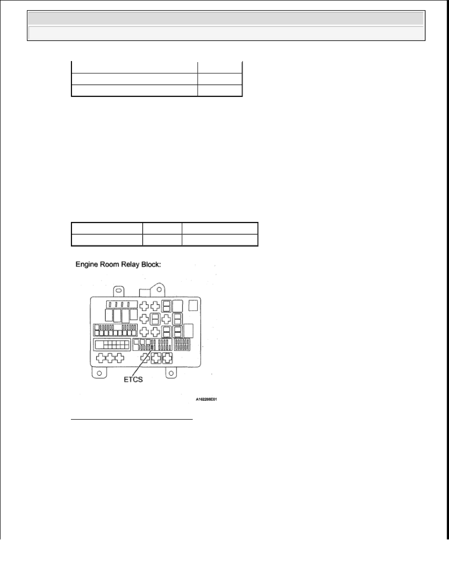
2. INSPECT FUSE (ETCS) 

a. Remove the ETCS fuse from the engine room relay block.  

b. Measure the resistance according to the value(s) in the table below. 

Standard resistance  

STANDARD RESISTANCE SPECIFICATION 

Fig. 208: Identifying ETCS Fuse 

NG : CHECK FOR SHORTS IN ALL HARNESSES AND CONNECTORS CONNECTED TO 
FUSE AND REPLACE FUSE
  

OK : Go to Next Step  

3. CHECK HARNESS AND CONNECTOR (ECM - ETCS FUSE, ETCS FUSE - BATTERY) 

a. Check the harness and connector between the ETCS fuse and ECM. 

1. Remove the ETCS fuse from the engine room relay block.  

2. Disconnect the D74 ECM connector.  

Result

Proceed To

Less than 11 V or higher than 14 V

A

11 to 14 V

B

Tester Connection Condition Specified Condition

ETCS fuse

Always

Below 1 ohms


2008 Toyota Tundra 

2008 ENGINE PERFORMANCE Engine Control System (2UZ-FE) - Tundra


3. Measure the resistance according to the value(s) in the table below. 

Standard resistance  

STANDARD RESISTANCE SPECIFICATION 

b. Check the harness and connector between the ETCS fuse and positive battery cable. 

1. Remove the ETCS fuse from the engine room relay block.  

2. Disconnect the cable from the positive (+) battery terminal.  

3. Measure the resistance according to the value(s) in the table below. 

Standard resistance  

STANDARD RESISTANCE SPECIFICATION 

Tester Connection

Condition Specified Condition

ETCS fuse terminal 2 - D74-41 (+BM)

Always

Below 1 ohms

ETCS fuse terminal 2 or D74-41 (+BM) - Body ground Always

10 kohms or higher

Tester Connection

Condition

Specified 

Condition

Positive battery cable - ETCS fuse terminal 1

Always

Below 1 ohms

Positive battery cable or ETCS fuse terminal 1 - Body 
ground

Always

10 kohms or higher


2008 Toyota Tundra 

2008 ENGINE PERFORMANCE Engine Control System (2UZ-FE) - Tundra


Fig. 209: Identifying ETCS Fuse & D74 ECM Connector 

NG : REPAIR OR REPLACE HARNESS OR CONNECTOR  

OK : Go to Next Step  

4. INSPECT ECM (+BM VOLTAGE) 

a. Disconnect the D74 ECM connector.  

b. Measure the voltage according to the value(s) in the table below. 

Standard voltage  

STANDARD VOLTAGE SPECIFICATION 

Tester Connection

Condition Specified Condition

D74-41 (+BM) - D74-81 (E1) Always

11 to 14 V


2008 Toyota Tundra 

2008 ENGINE PERFORMANCE Engine Control System (2UZ-FE) - Tundra


Fig. 210: Identifying D74 ECM Connector 

NG : REPAIR OR REPLACE HARNESS OR CONNECTOR (TERMINAL E1 - BODY 
GROUND)
  

OK : REPLACE ECM (See REMOVAL ) 

5. INSPECT BATTERY 

a. Check that the battery is not depleted. (See ON-VEHICLE INSPECTION ). 

OK: Battery is not depleted.  

NG : REPLACE BATTERY  

OK : Go to Next Step  

6. CHECK BATTERY TERMINAL 

a. Check that the battery terminals and ECM ground are not loose or corroded. 

OK: Battery terminals and ECM ground are not loose or corroded.  

NG : REPAIR OR REPLACE BATTERY TERMINAL  

OK : CHECK FOR INTERMITTENT PROBLEMS (See CHECK FOR INTERMITTENT 
PROBLEMS
 ) 

DTC P2119 THROTTLE ACTUATOR CONTROL THROTTLE BODY RANGE/PERFORMANCE 

DESCRIPTION 

The Electronic Throttle Control System (ETCS) is composed of the throttle actuator, Throttle Position (TP) 
sensor, Accelerator Pedal Position (APP) sensor, and ECM. The ECM operates the throttle actuator to regulate 


2008 Toyota Tundra 

2008 ENGINE PERFORMANCE Engine Control System (2UZ-FE) - Tundra


Content   ..  1410  1411  1412  1413   ..