Suzuki Grand Vitara JB416 / JB420 / JB419. Manual - part 216
 

  Index      Suzuki     Suzuki Grand Vitara JB416 / JB420 / JB419 - service repair manual 2007 year


Search            


Content   ..  214  215  216  217   ..


Suzuki Grand Vitara JB416 / JB420 / JB419. Manual - part 216


2B-8 Front Suspension: 

• Inspect bearing for wear, abnormal noise or gripping.

If defective, replace.

• Inspect coil spring seat for cracks or deformation.

If defective, replace.

• Inspect bump stopper for deterioration.

If defective, replace.

• Inspect rebound stopper and strut mount for wear, 

cracks or deformation.
If defective, replace.

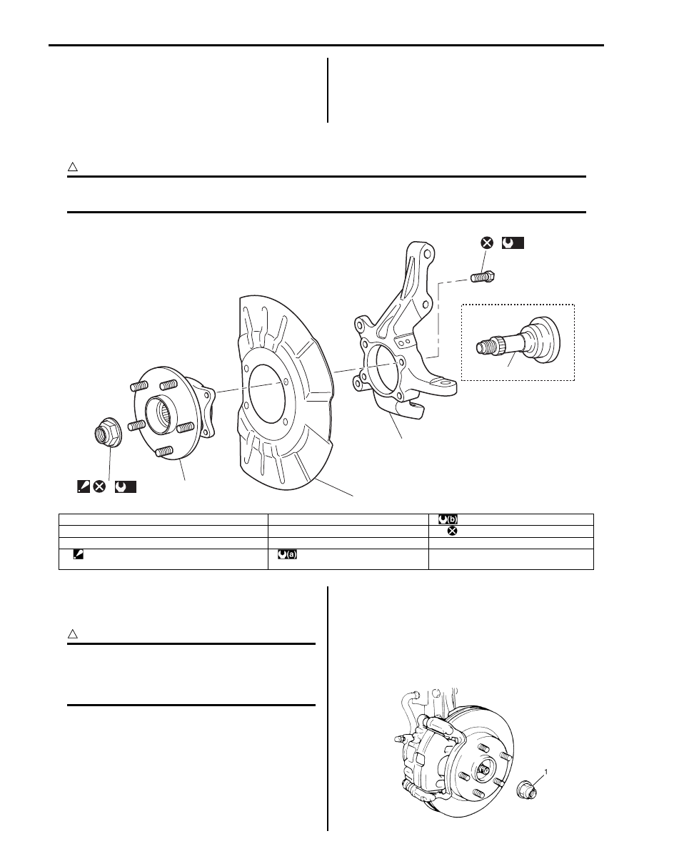
Front Wheel Hub Assembly and Steering Knuckle Components

S6JB0A2206006

CAUTION

!


Never disassemble front wheel hub assembly. Disassembly will spoil its original function. If faulty 
condition is found, replace it with new one.


Front Wheel Hub Assembly Removal and 
Installation

S6JB0A2206007

CAUTION

!


Never disassemble front wheel hub 
assembly. Disassembly will spoil its original 
function. If faulty condition is found, replace 
it with new one.


Removal

1) Hoist vehicle and remove wheel.
2) Uncaulk drive shaft nut (1).
3) Depress foot brake pedal and hold it. Remove drive 

haft nut (1).

4) Remove front wheel spindle (if equipped).

[A]

3

1

4

2

6

(a)

5

(b)

I6JB01220002-02

[A]: 2WD model

4. Dust cover

: 50 N

⋅m (5.0 kgf-m, 36.0 lb-ft)

1. Front wheel hub assembly

5. Wheel hub housing bolt

: Do not reuse.

2. Steering knuckle

6. front wheel spindle

3. Drive shaft nut

: Calk, after tightening.

: 220 N

⋅m (22.0 kgf-m, 159.5 lb-ft)

I5JB0A220013-01

Front Suspension:  2B-9

5) Remove caliper (1) with carrier.

NOTE
Hang removed caliper with a wire hook or the 
like (3) so as to prevent brake hose (4) from 
bending, twisting or tension.Do not depress 
brake pedal during pads removal.
Do not operate brake pedal with pads 
removed.


6) Pull brake disc (2) off by using two 8 mm bolts.

7) Remove wheel hub housing bolts (3), and then 

remove wheel hub assembly (1) and dust cover (2).

8) Remove hub bolts (1) with copper hammer or 

hydraulic press.

CAUTION

!


Never remove bolt unless replacement is 
necessary.
Be sure to use a new bolt for replacement.


Installation

1) Insert new hub bolt (1) in hub hole. Rotate hub bolt 

slowly to assure that serrations are aligned with 
those made by original bolt.

2) Apply grease to end face of inner ring (2) before front 

wheel nub (1) installation.

CAUTION

!


Do not apply the grease to the encoder 
section to avoid the encoder malfunction.


“A”:  Grease 99000–25010 (SUZUKI Super 
Grease A)

3) Install wheel hub (1) and dust cover (2) to steering 

knuckle.

4) Tighten wheel hub housing bolts (3) to specified 

torque.

Tightening torque
Wheel hub housing bolt (a):  50 N·m (5.0 kgf-m, 
36.5 lb-ft)

I5JB0A220014-01

1

2

3

3

I5JB0A220015-01

1

I5JB0A220016-01

1

I5JB0A220017-01

1

2, "A"

I5JB0A220018-01

3,(a)

3,(a)

2

1

I5JB0A220019-01

2B-10 Front Suspension: 

5) Install brake disk and brake caliper.
6) Tighten caliper carrier bolt to specified torque.

Tightening torque
Caliper carrier bolt:  85 N·m (8.5 kgf-m, 61.5 lb-ft)

7) Install front wheel spindle (if equipped).
8) Depress foot brake pedal and hold it there. Tighten 

new drive shaft nut (1) to specified torque.

Tightening torque
Drive shaft nut (a):  220 N·m (22.0 kgf-m, 159.5 
lb-ft)

CAUTION

!


Never reuse drive shaft nut (1).


9) Caulk drive shaft nut (1) as shown.

10) Tightening wheel nuts to specified torque.

Tightening torque
Wheel nut:  100 N·m (10.0 kgf-m, 72.5 lb-ft)

Steering Knuckle Removal and Installation

S6JB0A2206008

Removal

1) Hoist vehicle and remove wheel.
2) Remove Front wheel hub assembly referring to 

“Front Wheel Hub Assembly Removal and 
Installation”.

3) Disconnect tie-rod end from steering knuckle 

referring to Step 2) to 3) of “Removal” in “Tie-Rod 
End Removal and Installation in Section 6C”.

4) Disconnect front height sensor (if equipped) from 

suspension control arm for left side referring to 
“Height Sensor Removal and Installation (If 
Equipped) in Section 9B”
.

5) Remove wheel speed sensor from knuckle.
6) Remove steering knuckle ball joint nut then remove 

strut bracket bolts and nut.

7) Disconnect ball joint from steering knuckle with 

puller and then remove steering knuckle.

Installation
For installation, reverse removal procedure, noting the 
following instructions.

1) Connect steering knuckle to suspension control arm.
2) Install strut bracket bolts (2) and nuts (1) as shown in 

figure.

3) Tighten strut bracket nuts (1) to specified torque.

Tightening torque
Strut bracket nut (a):  135 N·m (13.5 kgf-m, 98.0 
lb-ft)

4) Tighten new suspension arm ball joint nut (1) to 

specified torque.

CAUTION

!


Never reuse the removed suspension arm 
ball joint nut.


Tightening torque
Suspension arm ball joint nut (a):  55 N·m (5.5 
kgf-m, 40.0 lb-ft)

5) Install front wheel speed sensor (2) and tighten 

wheel speed sensor bolt (3).

Tightening torque
Wheel speed sensor bolt (b):  11 N·m (1.1 kgf-m, 
8.0 lb-ft)

I5JB0A220021-01

F: Forward

I5JB0A220025-01

2

3,(b)

1,(a)

I5JB0A220026-01

Front Suspension:  2B-11

6) Connect front height sensor (if equipped) to 

suspension control arm for left side referring to 
“Height Sensor Removal and Installation (If 
Equipped) in Section 9B”.

7) Connect tie-rod end to steering knuckle referring to 

“Tie-Rod End Removal and Installation in Section 
6C”.

8) Install front wheel hub assembly and dust cover to 

steering knuckle referring to “Front Wheel Hub 
Assembly Removal and Installation”.

9) Check front wheel alignment adjust it as necessary. 

For check and adjustment procedures, refer to 
“Front Wheel Alignment Inspection and Adjustment”.

10) Adjust headlight auto levering system (if equipped), 

refer to “Initialization of Auto Leveling Headlight 
System in Section 9B”.

Front Wheel Hub, Disc, Nut and Bearing Check

S6JB0A2206009

• Inspect each wheel disc for dents, distortion and 

cracks.
A disc in badly damaged condition must be replaced.

• Check rust of installation face inside of wheel disc.

As rust affects adversely, remove it thoroughly.

• Check tightness of wheel nuts and, if necessary, 

retighten them to specified torque.

Tightening torque
Wheel nut (a):  100 N·m (10.0 kgf-m, 72.5 lb-ft)

• Check wear of wheel bearing. When measuring thrust 

play, apply a dial gauge to wheel hub as shown in 
figure.

Front wheel bearing thrust play
Limit: 0.1 mm (0.004 in.)

• Check wheel bearing noise and smooth wheel rotation 

by rotating wheel in figure.
If defective, replace bearing.

Suspension Control Arm Removal and 
Installation

S6JB0A2206010

Removal

1) Remove steering knuckle from suspension control 

arm referring to “Steering Knuckle Removal and 
Installation”.

2) Remove suspension control arm bolts (1).

Installation

1) Install suspension control arm bolts (1) and tighten 

suspension control arm nuts (2) temporarily by hand.

CAUTION

!


If reuse suspension control arm bolt and nut, 
apply engine oil to thread, bearing and trunk 
surface.


(a)

I5JB0A220029-01

I3RM0A220034-01

I2RH01220011-01

1

I5JB0A220031-01

1

2

I5JB0A220033-01


Content   ..  214  215  216  217   ..