Suzuki Grand Vitara JB416 / JB420 / JB419. Manual - part 214
 

  Index      Suzuki     Suzuki Grand Vitara JB416 / JB420 / JB419 - service repair manual 2007 year


Search            


Content   ..  212  213  214  215   ..


Suzuki Grand Vitara JB416 / JB420 / JB419. Manual - part 214


2A-3 Suspension General Diagnosis: 

Specifications

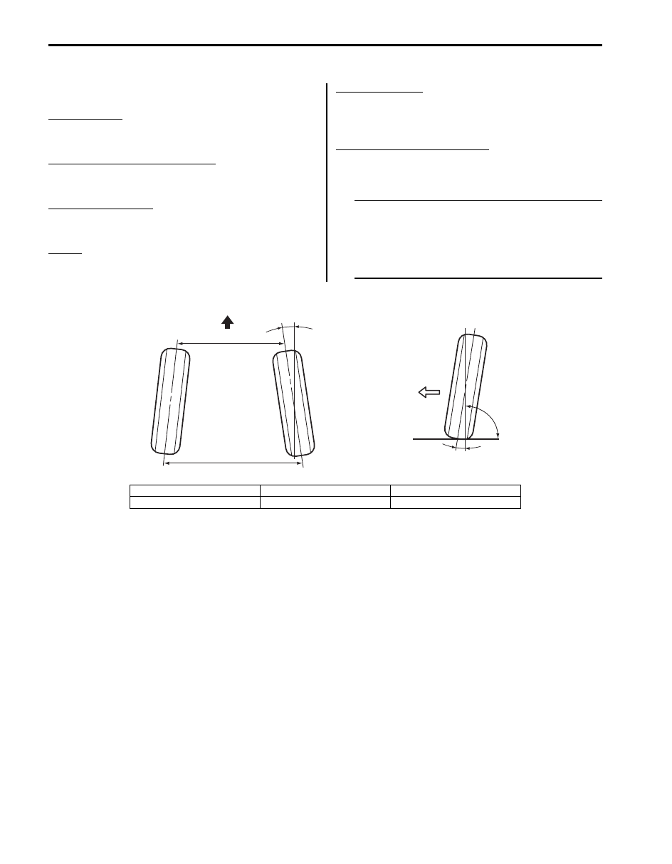
Wheel Alignment Specifications

S6JB0A2107001

Toe (“b” – “a”)
Front: 0.0 

± 2.0 mm (0 ± 0.0787 in.)

Rear: IN 6.0 

± 2.0 mm (0.2362 ± 0.0787 in.)

Toe (degree) (each wheel) (“d”)*1
Front: 0

° ± 5’

Rear: 0

° 14’ ± 5’

Camber (degree) “c”
Front: 0

° 00’ ± 1°

Rear: –1

° 15’ ± 30’

Caster
3door model: 2

° 40’

5door model: 2

° 30’

Side Slip Limit *1
Front: IN 1.5 to OUT 1.5 mm/m (IN 0.0591 to OUT 
0.0591 in./3.3 ft)
Rear: IN 7.5 mm/m (IN 0.2953 in./3.3 ft)

Steering angle (Turning angle)
Inside: 37.0

° ± 3°

Outside: 32.0

° ± 3°

NOTE

• Toe value in the specifications table was 

measured by using a toe-in gauge.

• As for front camber and caster, regulation 

is impossible.

*1: Reference information.


[A]

[B]

2

1

90˚

“c ”

“a”

“b”

F

“d ”

I6JB0B210001-02

[A]: Toe-in (Top view)

1. Center line of wheel

F: Forward

[B]: Camber (Front view)

2. Body center

Front Suspension:  2B-1

Suspension

Front Suspension

General Description

Front Suspension Construction

S6JB0A2201001

2

7

4

2

5

8

1

6

3

(b)

(c)

(d)

(e)

(f)

(g)

(a)

(a)

(h)

(h)

(b)

(b)

(f)

(g)

9

10

10

(a)

10

11

(a)

12

I6JB0A220001-03

1. Front strut assembly

8. Stabilizer bar joint

: 55 N

⋅m (5.5 kgf-m, 40.0 lb-ft)

2. Stabilizer bar

9. Strut nut

: Do not reuse caulking nut if used.

: 70 N

⋅m (7.0 kgf-m, 51.0 lb-ft)

3. Steering knuckle

10. Suspension frame bolt

: If bolt is reused, apply engine oil to thread, bearing and 
trunk surface.

: 220 N

⋅m (22.0 kgf-m, 159.5 lb-ft)

4. Suspension control arm

11. Suspension frame

: 65 N

⋅m (6.5 kgf-m, 47.0 lb-ft)

5. Front drive shaft

12. Strut bracket nut

: If nut is reused, apply engine oil to thread and bearing.

: 43 N

⋅m (4.3 kgf-m, 31.0 lb-ft)

6. Vehicle body

: 135 N

⋅m (13.5 kgf-m, 98.0 lb-ft)

: 60 N

⋅m (6.0 kgf-m, 43.5 lb-ft)

7.  Tie-rod

: 50 N

⋅m (5.0 kgf-m, 36.5 lb-ft)

: Do not reuse.

2B-2 Front Suspension: 

Front Wheel Alignment Construction

S6JB0A2201002

Among factors for front wheel alignment, only toe setting 
can be adjusted. Camber and caster are not adjustable. 
Therefore, should camber or caster be out of 
specification due to the damage caused by hazardous 
road conditions or collision, whether the damage is in 
body or in suspension should be determined and 
damaged body should be repaired or damaged 
suspension should be replaced.

Preliminary Checks Prior to Adjustment Front Wheel 
Alignment
Steering and vibration complaints are not always the 
result of improper wheel alignment. An additional item to 
be checked is the possibility of tire lead due to worn or 
improperly manufactured tires. “Lead” is the vehicle 
deviation from a straight path on a level road without 
hand pressure on the steering wheel. Refer to “Radial 
Tire Lead / Pull Description in Section 2D” in
 order to 
determine if the vehicle has a tire lead problem. Before 
making any adjustment affecting wheel alignment, the 
following checks and inspections should be made to 
ensure correctness of alignment readings and alignment 
adjustments:

• Check all tires for proper inflation pressures and 

approximately the same tread wear.

• Check for loose of ball joints. Check tie-rod ends; if 

excessive looseness is noted, it must be corrected 
before adjusting.

• Check for run-out of wheels and tires.
• Check vehicle trim heights; if it is out of limit and a 

correction is needed, it must be done before adjusting 
toe.

• Check for loose of suspension control arms.
• Check for loose or missing stabilizer bar attachments.
• Consideration must be given to excess loads, such as 

tool boxes. If this excess load is normally carried in 
vehicle, it should remain in vehicle during alignment 
checks.

• Consider condition of equipment being used to check 

alignment and follow manufacturer’s instructions.

• Regardless of equipment used to check alignment, 

vehicle must be placed on a level surface.

NOTE
To prevent possible incorrect reading of toe, 
camber or caster, vehicle front and rear end 
must be moved up and down a few times 
before inspection.


Repair Instructions

Front Wheel Alignment Inspection and 
Adjustment

S6JB0A2206001

Toe Inspection and Adjustment
Preparation for toe inspection and adjustment.
• Place vehicle in unloaded state on level surface.
• Set steering wheel in straight state.
• Check that inflation pressure of each tire is adjusted 

properly and wheel is free from deflection.

• Check that each suspension part is free from bend, 

dent, wear or damage in any other form.

• Check that ground clearance at the right and left is 

just about the same.

Inspection
Measure toe with toe-in gauge (1).
Toe should be within following specifications.
If toe is out of the specification, adjust toe properly.

Toe
IN 0 

± 2.0 mm (0 ± 0.0787 in.)

I2RH01220062-01

Front Suspension:  2B-3

Adjustment

1) Loosen right and left tie-rod end lock nuts (1) first.
2) Rotate right and left tie-rods (2) by the same amount 

to align toe to specification. In this adjustment, the 
lengths “A” of both right and left tie-rod should be 
equal.

NOTE
Before rotating tie-rods (2), apply grease 
between tie-rods and rack boots so that 
boots won’t be twisted.


3) After adjustment, tighten lock nuts (1) to specified 

torque.

Tightening torque
Tie-rod end lock nut (a):  65 N·m (6.5 kgf-m, 47.0 
lb-ft)

NOTE
Make sure that rack boots are not twisted.


Steering Angle Check and Adjustment
When tie-rod or tie-rod end was replaced, check toe and 
then also steering angle with turning radius gauge (1).
If steering angle is not correct, check whether right and 
left tie-rods length “A” are equal.

NOTE
If tie-rod lengths were changed to adjust 
steering angle, reinspect toe-in.


Steering angle
Inside: 37.0

° ± 3°

Outside: 32.0

° ± 3°

Reference Information
Side slip
When checked with side slip tester, side slip should 
satisfy following specification.

Side slip
IN 1.5 to OUT 1.5 mm/m (IN 0.0591 to OUT 0.0591 in. / 
3.3 ft)

If side slip is greatly different, toe or front wheel 
alignment may not be correct.

I5JB0A220002-01

I5JB0A220003-01


Content   ..  212  213  214  215   ..