Suzuki Grand Vitara JB416 / JB420 / JB419. Manual - part 215
 

  Index      Suzuki     Suzuki Grand Vitara JB416 / JB420 / JB419 - service repair manual 2007 year


Search            


Content   ..  213  214  215  216   ..


Suzuki Grand Vitara JB416 / JB420 / JB419. Manual - part 215


2B-4 Front Suspension: 

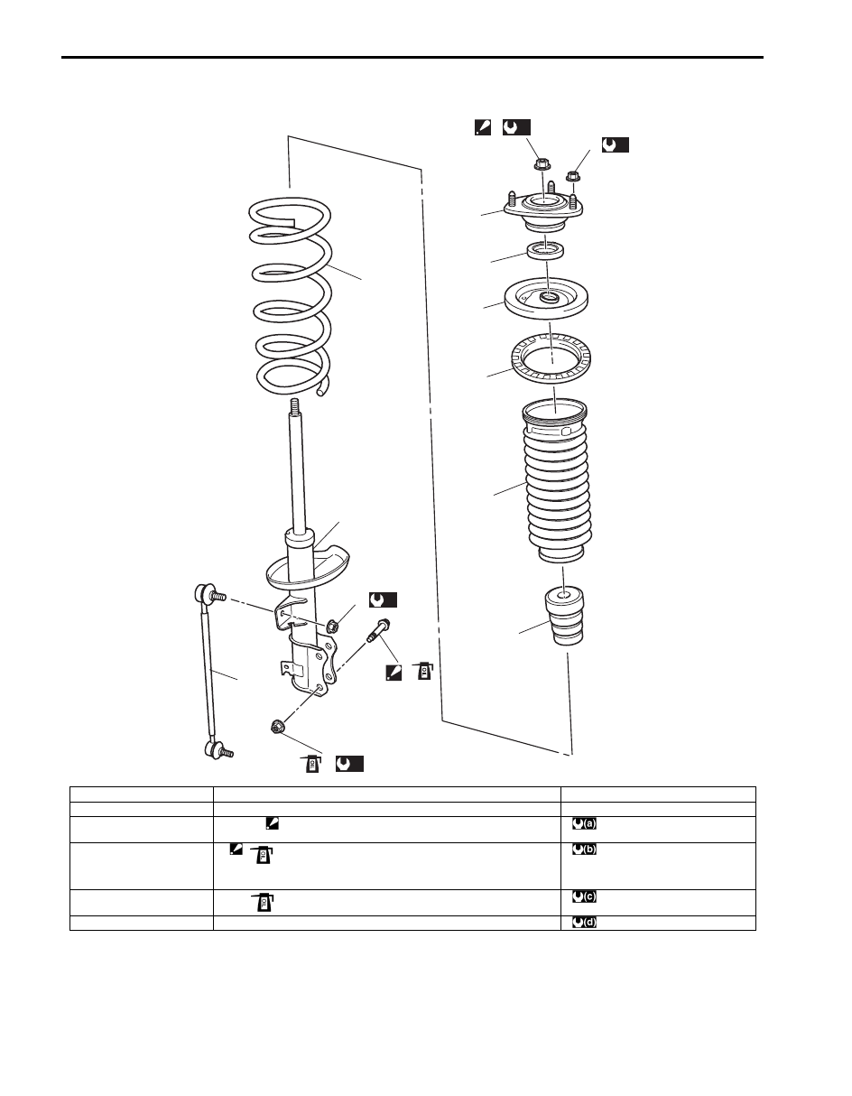
Front Strut Assembly Components

S6JB0A2206002

7

6

5

4

14

2

1

13

3

12

(a)

8

(b)

9

(c)

11

10

(d)

I6JB0A220002-01

1. Strut assembly

7. Strut support

13. Stabilizer joint

2. Coil spring

8. Strut support nut

14. Strut dust cover

3. Bump stopper

9. Strut nut

: Do not reuse caulking nut if used.

: 50 N

⋅m (5.0 kgf-m, 36.5 lb-ft)

4. Coil spring seat

10. Strut bracket bolt

: Insert from vehicle front side.
: If bolt is reused, apply engine oil to thread, bearing and trunk 
surface.

: 70 N

⋅m (7.0 kgf-m, 51.0 lb-ft)

5. Coil spring upper seat

11. Strut bracket nut

: If nut is reused, apply engine oil to thread and bearing.

: 135 N

⋅m (13.5 kgf-m, 98.0 lb-ft)

6. Strut bearing

12. Stabilizer joint nut

: 60 N

⋅m (6.0 kgf-m, 43.5 lb-ft)

Front Suspension:  2B-5

Front Strut Assembly Removal and Installation

S6JB0A2206003

Removal

NOTE
When servicing component parts of strut 
assembly, remove strut rod cap and then 
loosen strut nut a little before removing strut 
assembly. This will make service work easier. 
Note that the nut must not be removed at this 
point.


1) Hoist vehicle, allowing front suspension to hang free.
2) Remove wheel and disconnect stabilizer joint (1) 

from strut bracket.
When loosening joint nut, hold stud with hexagon 
wrench.

3) Remove brake hose mounting bolt (1) and remove 

brake hose (2) from bracket.

4) Disconnect front height sensor (if equipped) from 

suspension control arm for left side referring to 
“Height Sensor Removal and Installation (If 
Equipped) in Section 9B”.

5)  Remove wheel speed sensor harness clamp bolt (3) 

and then detach wheel speed sensor harness (5) 
from strut bracket as shown in figure.

6) Remove strut bracket bolts and nuts (4).

7) Remove strut support nuts (1).

NOTE
Hold strut by hand so that it will not fall off.


8) Remove strut assembly.

Installation
Install strut assembly by reversing removal procedure, 
noting the following instructions.
• Insert bolts in such direction as shown in figure.
• Tighten all fasteners to specified torque.

Tightening torque
Strut bracket nut (a):  135 N·m (13.5 kgf-m, 98.0 lb-
ft)
Brake hose mounting bolt (c):  25 N·m (2.5 kgf-m, 
18.0 lb-ft)
Stabilizer joint nut (d):  60 N·m (6.0 kgf-m, 43.5 lb-
ft)
Wheel speed sensor harness clamp bolt (e):  11 
N·m (1.1 kgf-m, 8.0 lb-ft)

1

I5JB0A220005-02

3

5

4

4

4

1

2

I5JB0A220006-01

1

I5JB0A220007-01

2B-6 Front Suspension: 

• Lower hoist and vehicle in unloaded condition, tighten 

strut support nuts (b) to specified torque.

Tightening torque
Strut support nut (b):  50 N·m (5.0 kgf-m, 36.5 lb-ft)

CAUTION

!


If bracket bolt and nut are reused, apply 
engine oil to thread, bearing and trunk 
surface.


NOTE

• Don’t twist brake hose and wheel speed 

sensor harness when installing them.

• Insert strut bracket bolt from vehicle 

forward.


• Tighten wheel nuts to specified torque.

Tightening torque
Wheel nut:  100 N·m (10.0 kgf-m, 72.5 lb-ft)

• After installation, confirm front wheel alignment and 

adjust auto leveling headlight system (if equipped) 
referring to “Initialization of Auto Leveling Headlight 
System in Section 9B”.

Front Strut Assembly Disassembly and 
Assembly

S6JB0A2206004

WARNING

!


Use a regular coil spring compressor and 
follow the operation procedure described in 
the Instruction Manual.
Otherwise, spring might come off and injure.


Disassembly

1) Attach special tool (A) to coil spring as shown. Turn 

special tool bolts alternately until coil spring tension 
is released. Rotate the strut around its axis to 
confirm that the coil spring is released or not.

Special tool
(A):  09943–25010

2) While keeping coil spring compressed, remove strut 

nut with special tools as shown.

Special tool
(A):  09900–00411
(B):  09900–00414
(C):  09941–56510

3) Disassemble strut assembly.

(b)

(e)

(d)

(a)

(a)

(c)

I5JB0A220008-01

(A)

I5JB0A220059-01

I5JB0A220060-01

Front Suspension:  2B-7

Assembly
For assembly, reverse disassembly procedure, noting 
the following instructions.

1) Compress coil spring with special tool (A) until total 

length becomes about 310 mm (12.2 in.) as shown.

Length
“a”: 310 mm (12.2 in.)

2) Install bump stopper onto strut rod. For installing 

direction, refer to the figure in “Front Strut Assembly 
Components”.

3) Install compressed coil spring to strut, and place coil 

spring end (2) onto spring lower seat (1) as shown.

NOTE
End of coil spring must not interfere with 
step of spring lower seat.


4) Pull strut rod as far up as possible and use care not 

to allow it to retract into strut.

5) Attach coil spring seat to coil spring upper seat and 

then install strut dust cover firmly.

6) Install coil spring upper seat with strut dust cover on 

coil spring and then spring upper seat (1) aligning 
“OUT” mark (3) on spring upper seat and center of 
strut bracket (2).

7) Install bearing (3), strut support (2) and strut nut (1) 

in this sequence.
Tighten strut nut (1) holding stud with special tools.

NOTE
If using caulking nut, do not reuse.


Special tool
(A):  09900–00411
(B):  09900–00414
(C):  09941–56510

Tightening torque
Strut nut (a):  70 N·m (7.0 kgf-m, 51.0 lb-ft)

Front Strut Assembly Check

S6JB0A2206005

• Inspect strut for oil leakage, damage or deformation.

If defect is found, replace strut as an assembly unit, 
because it can not be disassembled.

• Inspect strut function referring to the following 

procedures:

1) Check and adjust tire pressures as specified.
2) Bounce vehicle body up and down 3 or 4 times 

continuously by pushing front end of the vehicle side 
body to check strut.
Also, note how many times vehicle body rebounds to 
stop after force application.

3) Repeat the same procedure to the other strut to 

confirm that the both side struts equally respond.

If conditions of struts are in doubt, compare them with 
known-good vehicle or strut.

“a”

I6JB01220001-02

I4RS0A220011-01

I2RH01220019-01

I5JB0A220011-03

I4RS0A220014-01


Content   ..  213  214  215  216   ..