Suzuki Grand Vitara JB416 / JB420 / JB419. Manual - part 187
 

  Index      Suzuki     Suzuki Grand Vitara JB416 / JB420 / JB419 - service repair manual 2007 year


Search            


Content   ..  185  186  187  188   ..


Suzuki Grand Vitara JB416 / JB420 / JB419. Manual - part 187


1G-21 Fuel System: For Petrol Engine Model

Removal

1) Remove fuel tank from vehicle Referring to “Fuel 

Tank Removal and Installation: For Petrol Engine 
Model”

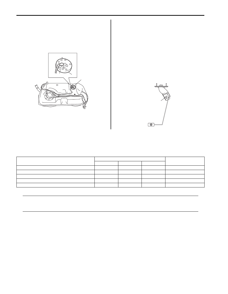
2) Disconnect sub fuel level sensor connector (1).
3) Remove sub fuel level sensor (2).

Installation
Reverse removal procedure for installation noting the 
following.
• Replace O-ring with new one using care not to 

damage it.

• Apply thin coat of fuel to O-ring, and then install sub 

fuel level sensor.

Sub Fuel Level Sensor Inspection

S6JB0A1716023

• Check sub fuel level sensor for damage.
• For inspection of sub fuel sensor (1), refer to “Fuel 

Level Sensor Inspection in Section 9C”.

Specifications

Tightening Torque Specifications

S6JB0A1717001

NOTE
The specified tightening torque is also described in the following.
“Fuel System Components: For Petrol Engine Model”
“Fuel Hose Disconnecting and Reconnecting: For Petrol Engine Model”


Reference:
For the tightening torque of fastener not specified in this section, refer to “Fastener Information in Section 0A”.

2

2

1

I5JB0A171029-01

1

I5JB0A171030-01

Fastening part

Tightening torque

Note

N

m

kgf-m

lb-ft

Fuel delivery pipe bolt

25

2.5 

18.0

)

Fuel pressure regulator bolt

11

1.1 

8.0

)

Fuel tank bolt

50

5.0 

36.5

)

Fuel filler hose clamp

2

0.2 

1.5

)

Fuel pump assembly bolt

11

1.1 

8.0

)

Fuel System: For Petrol Engine Model 1G-22

Special Tools and Equipment

Recommended Service Material

S6JB0A1718001

NOTE
Required service material is also described in the following.
“Fuel System Components: For Petrol Engine Model”


Special Tool

S6JB0A1718002

Material

SUZUKI recommended product or Specification

Note

Oil

SUZUKI DI O RING OIL(500CC)

P/No.: 99000–25320

)

09912–58413

09912–58421

Fuel pressure gauge set

Checking tool set

)

This kit includes the 
following items. 1. Tool body 
and washer, 2. Body plug, 3. 
Body attachment-1, 4. 
Holder, 5. Return hose and 
clamp, 6. Body attachment-2 
and washer, 7. Hose 
attachment-1, 8. Hose 
attachment-2)

09912–58442

09912–58490

Fuel pressure gauge

3-way joint & hose

This tool is included in fuel 
pressure gauge set (09912-
58413).)

)

09917–47011

09919–47020

Vacuum pump gauge

Quick joint remover

)

)

09930–88530

SUZUKI scan tool

Injector test lead

)

This kit includes following 
items. 1. Tech 2, 2. PCMCIA 
card, 3. DLC cable, 4. SAE 
16/19 adapter, 5. Cigarette 
cable, 6. DLC loop back 
adapter, 7. Battery power 
cable, 8. RS232 cable, 9. 
RS232 adapter, 10. RS232 
loop back connector, 11. 
Storage case, 12.)

1G-23 Fuel System: For Diesel Engine Model

For Diesel Engine Model

Precautions

Precautions on Fuel System Service

S6JB0A1720001

WARNING

!


• Before attempting service of any type on fuel system, the following should be always observed in 

order to reduce the risk of fire and personal injury.
– Disconnect negative (–) cable at battery.
– Do not smoke, and place no smoking signs near work area.
– Be sure to have CO

2

 fire extinguisher handy.

– Be sure to perform work in a well-ventilated area and away from any open flames (such as gas hot 

heater).

– Wear safety glasses.
– To relieve fuel vapor pressure in fuel tank, remove fuel filler cap from fuel filler neck and then 

reinstall it.

– As fuel feed line is still under high fuel pressure even after engine was stopped, loosening or 

disconnecting fuel feed line directly may cause dangerous spout of fuel to occur where loosened 
or disconnected. Before loosening or disconnecting fuel high presser line, make sure to relieve 
fuel pressure referring to “Fuel Pressure Relief Procedure: For Diesel Engine Model”.

– A small amount of fuel may be released after the fuel line is disconnected. In order to reduce the 

chance of personal injury, cover the fitting to be disconnected with a lint-free cloth. Be sure to put 
that cloth in an approved container when disconnection is completed.

– When connecting fuel pipe flare nut, first tighten flare nut by hand and then tighten it to specified 

torque.

– The system can inject the diesel fuel into the engine at a pressure up to 160,000 kPa (1,600 kg/

cm

2

, 22,760 psi). Before carrying out any work, check that the injector rail is not under pressure 

and that the fuel temperature is not too high.

– Do not place your hand near to a leak on the high pressure fuel circuit.
– Do not run engine with disconnecting fuel pipe and/or removing fuel system components.
– Do not expose removed fuel system parts to dust. Keep always clean.
– When servicing the fuel tank, it should be treated with respect, with no contact with sharp edges 

or hot surfaces. In addition, the fuel tank should not be dropped since fuel tank, fuel pump and 
other components can be damaged by the impact. If dropped, all components should be replaced 
because there is a risk of damage.

– Note that fuel hose connection varies with each type of pipe. Be sure to connect and clamp each 

hose correctly referring to “Fuel Hose Disconnecting and Reconnecting: For Diesel Engine 
Model”.
After connecting, mark sure that it has no twist or kink.

• Fuel vapor is hazardous. It can very easily ignite, causing serious injury and damage. Always keep 

sparks and flames away from fuel. Fuel line spills and leaks are dangerous. Fuel can ignite and 
cause serious injuries or death and damage.


Fuel System: For Diesel Engine Model 1G-24

• The fuel system must be checked for leaks after service work referring to “Fuel Leakage Check Procedure: For 

Diesel Engine Model”.

• The fuel system is very sensitive to contamination. The risks caused by the introduction of contamination are:

– damage or destruction of the high pressure injection system and the engine.
– seizing or leaking of a component.

• When servicing on the high pressure direct injection system, must be performed under very clean conditions.

This means that no impurities (particles a few microns in side) get into the system during dismantling or into the 
circuits via the fuel unions.

• The cleanliness principle must be applied from the fuel filter to the injectors.
• Contamination is caused by:

– metal or plastic chips,
– paint,
– fibres: boxes, brushes, paper, clothing, cloths,
– foreign bodies such as hair,
– ambient air,
– etc.

• It is not possible to clean the engine using a high pressure washer because of the risk of damaging connections.

In addition, moisture may collect in the connectors and create electrical connection problems.

• The technician should wear clean overalls.
• Ensure that you have the plug caps (1) for the unions to be opened. Plug caps are to be used once only. After use, 

they must be thrown away (once used they are soiled and cleaning is not sufficient to make them reusable).
Unused plug caps must be thrown away, also.

NOTE

• Plug cap set is available as a spare part.
• Plug unions as soon as possible when removing / disconnecting fuel system component in order to 

prevent dust from invading.
Similarly, do not remove plug cap immediately before when installing / connecting fuel system 
component.


Content   ..  185  186  187  188   ..