Suzuki Grand Vitara JB416 / JB420 / JB419. Manual - part 186
 

  Index      Suzuki     Suzuki Grand Vitara JB416 / JB420 / JB419 - service repair manual 2007 year


Search            


Content   ..  184  185  186  187   ..


Suzuki Grand Vitara JB416 / JB420 / JB419. Manual - part 186


1G-17 Fuel System: For Petrol Engine Model

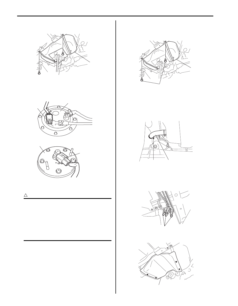
12) Support fuel tank (1) with jack (2) and remove its 

mounting bolts.

13) For M16 engine, lower fuel tank a little as to 

disconnect connectors (1) of fuel pump (2) and sub 
fuel level gauge (3), then remove fuel tank.

Installation

CAUTION

!


• When connecting joint, clean outside 

surfaces of pipe where joint is to be 
inserted, push joint into pipe till joint lock 
clicks and check to ensure that pipes are 
connected securely, or fuel leak may 
occur.

• Never let the fuel hoses touch the ABS 

sensor harness (if equipped).


1) If parts have been removed from fuel tank, install 

them before installing fuel tank to vehicle.

2) Raise fuel tank (1) with jack, and connect connectors 

of fuel pump and sub fuel level gauge and clamp 
wire harness.

3) Install fuel tank to vehicle.

Tightening torque
Fuel tank bolt (a):  50 N·m (5.0 kgf-m, 36.5 lb-ft)

4) Connect fuel filler hose (1) and breather hose to filler 

neck as shown in figure, and clamp them securely.

Tightening torque
Fuel filler hose clamp (a):  2 N·m (0.2 kgf-m, 1.5 
lb-ft)

5) Connect fuel feed hoses (1) to each pipe as shown 

in figure, and clamp them securely referring to “Fuel 
Hose Disconnecting and Reconnecting: For Petrol 
Engine Model”
.

6) Install fuel tank cover (1).

1

2

I5JB0A171018-01

1

3

2

1

I5JB0A171019-01

1

(a)

I5JB0A171020-01

1

(a)

I5JB0A171021-01

1

I5JB0A171022-01

1

I5JB0A171017-01

Fuel System: For Petrol Engine Model 1G-18

7) Install parking brake cable clamp to fuel tank cover 

referring to “Parking Brake Cable Location in Section 
4D”

8) Install rear propeller shaft referring to “Propeller 

Shaft Removal and Installation in Section 3D”

9) Install exhaust center pipe referring to “Exhaust 

System Components: For Petrol Engine Model in 
Section 1K”
.

10) Connect negative cable at battery.

11) With engine OFF, turn ignition switch to ON position 

and check for fuel leaks.

Fuel Tank Inspection

S6JB0A1716016

After removing fuel tank, check hoses and pipes 
connected to fuel tank for leaks, loose connections, 
deterioration or damage. Also check fuel pump 
assembly gaskets for leaks, visually inspect fuel tank for 
leaks and damage.
Replace any damaged or malconditioned parts.

Fuel Tank Purging Procedure

S6JB0A1716017

WARNING

!


• Before starting the following procedure, be 

sure to observe “Precautions on Fuel 
System Service: For Petrol Engine Model” 
in order to reduce the risk or fire and 
personal injury.

• This purging procedure will not remove all 

fuel vapor.
Do not attempt any repair on tank using 
heat of flame as an explosion resulting in 
personal injury could occur.


CAUTION

!


Never remain water in fuel tank after washing, 
or fuel tank inside will get corrosion.


The following procedure are used for purging fuel tank.

1) After removing fuel tank, remove all hoses, pipes, 

sub fuel level gauge and fuel pump assembly from 
fuel tank.

2) Drain all remaining fuel from tank.
3) Place fuel tank to flushing area.
4) Fill tank with warm water or tap water, and agitate 

vigorously and drain. Repeat this washing until 
inside of tank is clean. Replace tank if its inside is 
rusty.

5) Completely flush out remaining water after washing.

Fuel Pump On-Vehicle Inspection

S6JB0A1716018

WARNING

!


Before starting the following procedure, be 
sure to observe “Precautions on Fuel System 
Service: For Petrol Engine Model” in or
der to 
reduce the risk or fire and personal injury.


1) Remove filler cap and turn ON ignition switch (2). 

Then fuel pump operating sound should be heard 
from fuel filler (1) for about 2 seconds and stop. Be 
sure to reinstall fuel filler cap after checking.
If the check result is not satisfactory, go to “Fuel 
Pump and Its Circuit Check: For Petrol Engine Model 
in Section 1A”.

2) Turn OFF ignition switch and leave over 10 minutes 

as it is.

3) Fuel pressure should be felt at fuel feed hose (1) for 

about 2 seconds after ignition switch ON.
If fuel pressure is not felt, go to “Fuel Pressure 
Check: For Petrol Engine Model in Section 1A”.

[A]. For M16 engine model
[B]. For J20 engine model

IVSY01170013-01

[A]

[B]

1

1

I5JB0A171023-01

1G-19 Fuel System: For Petrol Engine Model

Fuel Pump Assembly Removal and Installation

S6JB0A1716019

WARNING

!


Before starting the following procedure, be 
sure to observe “Precautions on Fuel System 
Service: For Petrol Engine Model” in o
rder to 
reduce the risk or fire and personal injury.


Removal

1) Remove fuel tank from vehicle Refer to “Fuel Tank 

Removal and Installation: For Petrol Engine Model”.

2) Disconnect fuel feed pipe (1) and fuel return pipe (3) 

from fuel pump assembly (2) referring to “Fuel Hose 
Disconnecting and Reconnecting: For Petrol Engine 
Model”.

3) Disconnect fuel suction hose (2) referring to “Fuel 

Hose Disconnecting and Reconnecting: For Petrol 
Engine Model”.

4) Remove fuel pump assembly (1) from fuel tank.

Installation

CAUTION

!


When connecting joint, clean outside surface 
of pipe where joint is to be inserted, push 
joint into pipe till joint lock clicks and check 
to ensure that pipes are connected securely, 
or fuel leak may occur.


1) Clean mating surfaces of fuel pump assembly (1) 

and fuel tank.

2) Put plate (2) on fuel pump assembly (1) by matching 

the protrusion of fuel pump assembly (3) to plate 
hole (4) as shown.

3) Install new gasket (2) and fuel pump assembly (1) 

with plate (3) to fuel tank (4).

Tightening torque
Fuel pump assembly bolt (a):  11 N·m (1.1 kgf-m, 
8.0 lb-ft)

4) Connect fuel feed pipe (1) (pipe joint) and fuel return 

pipe (3) (pipe joint) to fuel pump assembly (2).

5) Install fuel tank to vehicle. Refer to “Fuel Tank 

Removal and Installation: For Petrol Engine Model”.

3

1

2

I5JB0A171024-01

2

1

I5JB0A170005-01

3

1

2

4

I5JB0A171025-01

3

1

2

(a)

4

I3RM0A170023-01

3

1

2

I5JB0A171024-01

Fuel System: For Petrol Engine Model 1G-20

Main Fuel Level Sensor Removal and 
Installation

S6JB0A1716020

CAUTION

!


• Do not touch resister plate (1) and deform 

arm (2). It may cause main fuel level sensor 
to fail.

• Be very careful not to cause damage to 

fuel tube installed section (sealed section 
in bore). If it be damaged, replace it with 
new one, or fuel will leak from the part.


Removal

1) Remove fuel pump assembly from fuel tank referring 

to “Fuel Pump Assembly Removal and Installation: 
For Petrol Engine Model”.

2) Disconnect main fuel level sensor connector (3).
3) With pressing snap-fit part (2), remove main fuel 

level sensor (1) by sliding it in the arrow direction as 
shown in figure.

Installation
Reverse removal procedure for installation.

Fuel Pump Inspection

S6JB0A1716021

• Check fuel pump assembly for damage.
• Check fuel suction filter for evidence of dirt and 

contamination.
If present, replace or clean and check for presence of 
dirt in fuel tank.

• For electrical circuit, refer to “Fuel Pressure Check: 

For Petrol Engine Model in Section 1A”.

• For inspection of main fuel level sensor (1), refer to 

“Fuel Level Sensor Inspection in Section 9C”.

Sub Fuel Level Sensor Removal and Installation

S6JB0A1716022

CAUTION

!


• Do not touch resister plate (1) and deform 

arm (2). It may cause sub fuel level sensor 
to fail.


1

2

I4RS0A170016-01

1

3

1

2

I5JB0A171026-01

1

I5JB0A171027-01

2

1

I5JB0A171028-01


Content   ..  184  185  186  187   ..