Suzuki Grand Vitara JB416 / JB420 / JB419. Manual - part 185
 

  Index      Suzuki     Suzuki Grand Vitara JB416 / JB420 / JB419 - service repair manual 2007 year


Search            


Content   ..  183  184  185  186   ..


Suzuki Grand Vitara JB416 / JB420 / JB419. Manual - part 185


1G-13 Fuel System: For Petrol Engine Model

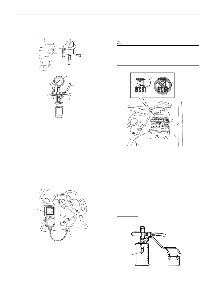
4) Connect special tool (test lead) to injector.

Special tool
(C):  09930–88530

5) Install suitable vinyl tube onto injector nozzle to 

prevent fuel from splashing out when injecting.

6) Put graduated cylinder under injector.
7) Operate fuel pump and apply fuel pressure to 

injector as follows:
a) When using scan tool:

i)

Connect scan tool to DLC with ignition switch 
OFF.

ii) Turn ignition switch ON, clear DTC and 

select “MISC TEST” mode on scan tool.

iii) Turn fuel pump ON by using scan tool.

Special tool
(A):  SUZUKI scan tool

b) When not using scan tool:

i)

Remove fuel pump relay from connector.

ii) Connect two terminals of relay connector 

using service wire (1) as shown in the figure.

CAUTION

!


Check to make sure that connection is made 
between correct terminals. Wrong 
connection can cause damage to ECM, wire 
harness, etc.


iii) Turn ignition switch ON.

8) Apply battery voltage to injector (1) for 15 seconds 

and measure injected fuel volume with graduated 
cylinder. Test each injector two or three times.

Reference injected fuel volume
(For M16 engine model) Approx. 46 cc / 15 sec. 
(1.62/1.55 US/Imp oz / 15 sec.)
(For J20 engine model) Approx. 65 cc / 15 sec. 
(2.20/2.29 US/Imp oz / 15 sec.)

9) Check fuel leakage from injector nozzle. Do not 

operate injector for this check (but fuel pump should 
be at work). If fuel leaks (1) more than the following 
specifications, replace.

Fuel leakage
Less than 1 drop/min.

A

B

C

1

A

I5JB0A170004-02

(A)

I5JB0A171009-01

1

I5JB0A171010-02

I2RH0B170013-01

Fuel System: For Petrol Engine Model 1G-14

Fuel Pressure Regulator Removal and 
Installation

S6JB0A1716010

WARNING

!


Before starting the following procedure, be 
sure to observe “Precautions on Fuel System 
Service: For Petrol Engine Model”in ord
er to 
reduce the risk or fire and personal injury.


Removal

1) Relieve fuel pressure according to “Fuel Pressure 

Regulator Inspection: For Petrol Engine Model”

2) Disconnect negative cable at battery.
3) Disconnect fuel return hose (1) and vacuum hose (2) 

from fuel pressure regulator.

4) Remove fuel pressure regulator (3) from delivery 

pipe.

Installation
Reverse removal procedure for installation noting the 
following.
• Replace O-ring with new one using care not to 

damage it.

• Apply thin coat of fuel to O-ring and then install fuel 

pressure regulator (1) to delivery pipe.

• Tighten fuel pressure regulator bolts to specified 

torque.

Tightening torque
Fuel pressure regulator bolt (a):  11 N·m (1.1 kgf-
m, 8.0 lb-ft)

• After installation, with engine OFF and ignition switch 

ON, check for fuel leaks around fuel line connection.

Fuel Pressure Regulator Inspection

S6JB0A1716011

Confirm fuel pressure of fuel line is decreased when fuel 
pressure regulator is applied negative pressure by 
special tool.

Special tool
(A):  09917–47011

1

2

3

I5JB0A171011-02

(a)

1

I5JB0A171012-01

I5JB0A171013-01

1G-15 Fuel System: For Petrol Engine Model

Fuel Filler Cap Inspection

S6JB0A1716012

WARNING

!


Before starting the following procedure, be 
sure to observe “Precautions on Fuel System 
Service: For Petrol Engine Model” in o
rder to 
reduce the risk or fire and personal injury.


Remove cap (1), and check gasket for even filler neck 
imprint, and deterioration or any damage. If gasket (2) is 
in malcondition, replace cap.

NOTE
If cap requires replacement, only a cap with 
the same features should be used. Failure to 
use correct cap can result in fire and 
personal injury.


Fuel Tank Inlet Valve Removal and Installation

S6JB0A1716013

WARNING

!


Before starting the following procedure, be 
sure to observe “Precautions on Fuel System 
Service: For Petrol Engine Model” in o
rder to 
reduce the risk or fire and personal injury.


Removal

1) Remove fuel filler cap.
2) Insert hose of a hand operated pump into fuel filler 

hose (1) and drain fuel in space “A” as shown in 
figure.

CAUTION

!


Do not force pump hose into fuel tank, or 
pump hose may damage to fuel tank inlet 
valve (2).


3) Hoist vehicle, and remove clamp (2) and fuel filler 

hose (1) from fuel filler neck.

4) Remove fuel tank inlet valve (1) using flat head rod 

(2) or the like.

CAUTION

!


Be careful not to damage fuel tank inlet valve 
(1) with flat head rod (2) or the like.


Installation

1) Install fuel tank inlet valve (1) to fuel tank.

2) Install fuel filler hose (1) to fuel tank and secure it 

with clamp (2).
For proper installation, refer to “Fuel Hose 
Disconnecting and Reconnecting: For Petrol Engine 
Model”
.

I2RH01170008-01

IYSQ01170010-01

1

2

I5JB0A171014-01

I2RH0B170017-01

I2RH0B170018-01

1

2

I5JB0A171014-01

Fuel System: For Petrol Engine Model 1G-16

3) Lower vehicle and install fuel filler cap.

Fuel Tank Inlet Valve Inspection

S6JB0A1716014

WARNING

!


Before starting the following procedure, be 
sure to observe “Precautions on Fuel System 
Service: For Petrol Engine Model” in o
rder to 
reduce the risk or fire and personal injury.


Check fuel tank inlet valve for the following.
If any damage or malfunction is found, replace.
• Damage
• Smooth opening and closing

Fuel Tank Removal and Installation

S6JB0A1716015

WARNING

!


Before starting the following procedure, be 
sure to observe “Precautions on Fuel System 
Service: For Petrol Engine Model” in o
rder to 
reduce the risk or fire and personal injury.


Removal

1) Relieve fuel pressure in fuel feed line according to 

“Fuel Pressure Relief Procedure: For Petrol Engine 
Model”.

2) Disconnect negative cable at battery.
3) Hoist vehicle.
4) Remove exhaust center pipe.
5) Remove rear propeller shaft referring to “Propeller 

Shaft Removal and Installation in Section 3D”

6) With cable connected, detach parking brake cable 

clamp from fuel tank cover referring to “Parking 
Brake Cable Location in Section 4D”

7) Disconnect fuel filler hose and breather hose from 

filler neck referring to “Fuel Tank Inlet Valve Removal 
and Installation: For Petrol Engine Model”
.

8) For J20 engine, disconnect fuel pump connector (1).

9) Due to absence of fuel tank drain plug, drain fuel 

tank by pumping fuel out through fuel tank filler.
Use hand operated pump device to drain fuel tank.

CAUTION

!


• Do not force pump hose into fuel tank, or 

pump hose may damage fuel tank inlet 
valve.

• Never store fuel in an open container due 

to possibility of fire or explosion.


10) Disconnect fuel pipe joint and fuel hoses (1) from 

fuel pipes (2) referring to “Fuel Hose Disconnecting 
and Reconnecting: For Petrol Engine Model”.

11) Remove fuel tank cover (1).

I5JB0A170009-01

1

I5JB0A171015-01

2

1

I5JB0A171016-01

1

I5JB0A171017-01


Content   ..  183  184  185  186   ..