Suzuki Grand Vitara JB416 / JB420 / JB419. Manual - part 75
 

  Index      Suzuki     Suzuki Grand Vitara JB416 / JB420 / JB419 - service repair manual 2007 year


Search            


Content   ..  73  74  75  76   ..


Suzuki Grand Vitara JB416 / JB420 / JB419. Manual - part 75


1A-247 Engine General Information and Diagnosis: For Petrol Engine Model

Fuel Injector Circuit Check

S6JB0A1114082

Wiring Diagram

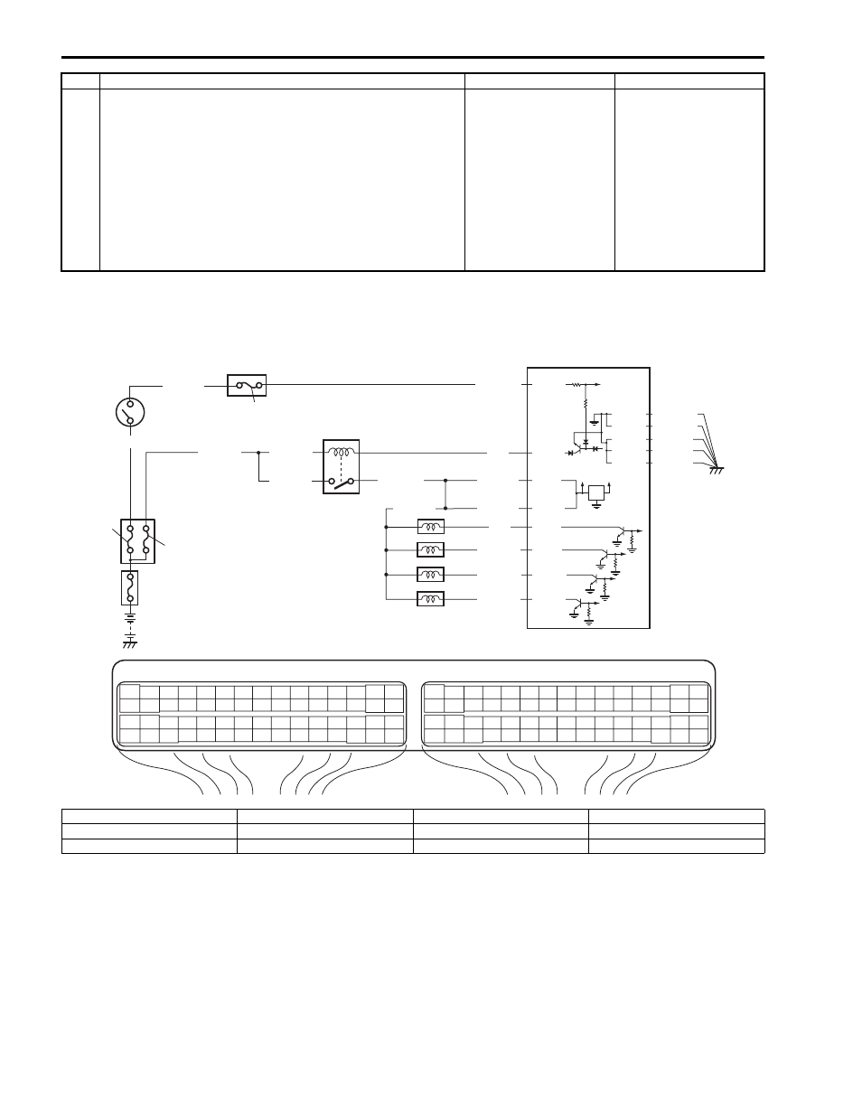
12 Sensor 5 V power source circuit check

1) Disconnect connectors from ECM, TP sensor, MAP 

sensor, A/C refrigerant pressure sensor (if equipped with 
A/C), electric load current sensor (for J20 engine) and 
accelerator pedal position (APP) sensor with ignition 
switch turned OFF.

2) Measure each resistance between “C37-14”, “E23-56”, 

“E23-54” and “C37-53” terminal of ECM connector and 
vehicle body ground.

Is each resistance infinity?

Check internal short 
circuit of TP sensor, 
MAP sensor, A/C 
refrigerant pressure 
sensor (if equipped with 
A/C), electric load 
current sensor (for J20 
engine) and/or 
accelerator pedal 
position (APP) sensor.

“GRY/RED”, “WHT” 
and/or “ORN/BLU” wire 
is shorted to ground 
circuit.

Step

Action

Yes

No

BLK/WHT

BLU/BLK

BLU/BLK

WHT/GRN

BLK/RED

BLK/RED

BLK/RED

BLK/YEL

BLU

12V

5V

9

2

8

3

E23-29  

E23-1  

E23-60  

10

E23

C37

3

4

18

19

5

6

7

10

11

17

20

47

46

49

50

51

21

22

52

16

25

9

24

14
29

55

57

54 53

59

60

58

2

26

27

28

15
30

56

48

32

31

34

35

36

37

40

42

39 38

44

45

43

41

33

1

12

13

23

8

3

4

18

19

5

6

7

10

11

17

20

47

46

49

50

51

21

22

52

16

25

9

24

14
29

55

57

54 53

59

60

58

2

26

27

28

15
30

56

48

32

31

34

35

36

37

40

42

39 38

44

45

43

41

33

1

12

13

23

8

C37-1  

C37-2  

C37-16  

C37-17  

BLU/BLK

BLU/BLK

PNK

PNK/GRN

PNK/BLU

PNK/BLK

E23-16  

4

5

6

7

1

11

C37-15  

C37-29  
C37-48  

BLK/ORN

C37-58  

C37-30  BLK/ORN

BLK/YEL
BLK/YEL
BLK/YEL

I5JB0A110101-01

1. Fuse box No.2

4. No.1 injector

7. No.4 injector

10. “FI” fuse

2. Main relay

5. No.2 injector

8. “IG COIL” fuse

11. “IGN” fuse

3. ECM

6. No.3 injector

9. Ignition switch

Engine General Information and Diagnosis: For Petrol Engine Model 1A-248

Troubleshooting

NOTE

• Before performed troubleshooting, be sure to read the “Precautions of ECM Circuit Inspection: For 

Petrol Engine Model”.

• When measuring circuit voltage, resistance and/or pulse signal at ECM connector, connect the 

special tool to ECM and/or the ECM connectors referring to “Inspection of ECM and Its Circuits: For 
Petrol Engine Model”.


Step

Action

Yes

No

1

Fuel injector check for operating sound
1) Using sound scope, check each injector for operating 

sound at engine cranking.

Do all 4 injector make operating sound?

Fuel injectors circuit is 
in good condition.

Go to Step 2.

2

Fuel injector resistance check
1) Disconnect connectors from fuel injectors with ignition 

switch turned OFF.

2) Check for proper connection to fuel injector at each 

terminals.

3) If OK, check all 4 fuel injectors for resistance referring to 

“Fuel Injector On-Vehicle Inspection: For Petrol Engine 
Model in Section 1G”.

Are all injectors in good condition?

Go to Step 3.

Faulty fuel injector.

3

Fuel injector insulation resistance check
1) Check that there is insulation between each fuel injector 

terminal and engine ground.

Is there insulation?

Go to Step 4.

Faulty fuel injector.

4

Fuel injector power supply check
1) Measure voltage between each “BLU/BLK” wire terminal 

of fuel injector connector and engine ground with ignition 
switch turned ON.

Is voltage 10 – 14 V?

Go to Step 5.

“BLU/BLK” wire is open 
or shorted to ground 
circuit.
If it is in good condition, 
go to “ECM Power and 
Ground Circuit Check: 
For Petrol Engine 
Model”.

5

Wire circuit check
1) Turn OFF ignition switch.
2) Disconnect connectors from ECM.
3) Measure resistance between each “PNK”, “PNK/BLK”, 

“PNK/GRN”, “PNK/BLU” wire terminal of fuel injector 
connector and vehicle body ground.

Is resistance infinity?

Go to Step 6.

“PNK”, “PNK/BLK”, 
“PNK/GRN” and/or 
“PNK/BLU” wire(s) are 
shorted to ground.

6

Wire circuit check
1) Measure voltage between each “PNK”, “PNK/BLK”, 

“PNK/GRN”, “PNK/BLU” wire terminal of fuel injector 
connector and vehicle body ground with ignition switch 
turned ON.

Is voltage 0 V?

Go to Step 7.

“PNK”, “PNK/BLK”, 
“PNK/GRN” and/or 
“PNK/BLU” wire(s) are 
shorted to power supply 
circuit.

1A-249 Engine General Information and Diagnosis: For Petrol Engine Model

Fuel Pump and Its Circuit Check

S6JB0A1114083

Wiring Diagram

7

Fuel injector drive signal check
1) Connect connectors to each fuel injector and ECM with 

ignition switch turned OFF.

2) Turn ON ignition switch.
3) Measure voltage between each “C37-1”, “C37-2”, “C37-

16”, “C37-17” terminal of ECM connector and vehicle 
body ground.

Is voltage 10 – 14 V?

Check fuel injector 
referring to “Fuel 
Injector Inspection: For 
Petrol Engine Model in 
Section 1G”.
If check result is 
satisfactory, substitute a 
known-good ECM and 
recheck.

“PNK”, “PNK/BLK”, 
“PNK/GRN” and/or 
“PNK/BLU” wire(s) are 
open circuit.

Step

Action

Yes

No

E23-1

E23-60

E23-15

BLU

BLU/BLK

BLK/RED

BLK/RED

BLU/BLK

E23-29

BLK/WHT

WHT/GRN

BLK/WHT

BLK/WHT

PNK

BLK

WHT/GRN

BLK/YEL

7

6

4

3

2

5

E23

C37

3

4

18

19

5

6

7

10

11

17

20

47

46

49

50

51

21

22

52

16

25

9

24

14
29

55

57

54 53

59

60

58

2

26

27

28

15
30

56

48

32

31

34

35

36

37

40

42

39 38

44

45

43

41

33

1

12

13

23

8

3

4

18

19

5

6

7

10

11

17

20

47

46

49

50

51

21

22

52

16

25

9

24

14
29

55

57

54 53

59

60

58

2

26

27

28

15
30

56

48

32

31

34

35

36

37

40

42

39 38

44

45

43

41

33

1

12

13

23

8

BLK/RED

1

E23-16

BLU/BLK

BLU/BLK

C37-15  

C37-29  
C37-48  

BLK/ORN

C37-58  

C37-30  BLK/ORN

BLK/YEL
BLK/YEL
BLK/YEL

8

9

I5JB0A110102-01

1. Fuse box No.2

4. Fuel pump relay

7. Ignition switch

2. Main relay

5. Fuel pump

8. “FI” fuse

3. ECM

6. “IG COIL” fuse

9. “IGN” fuse

Engine General Information and Diagnosis: For Petrol Engine Model 1A-250

Troubleshooting

NOTE

• Before performed troubleshooting, be sure to read the “Precautions of ECM Circuit Inspection: For 

Petrol Engine Model”.

• When measuring circuit voltage, resistance and/or pulse signal at ECM connector, connect the 

special tool to ECM and/or the ECM connectors referring to “Inspection of ECM and Its Circuits: For 
Petrol Engine Model”.


Step

Action

Yes

No

1

Fuel pump control system check for operation

Is fuel pump heard to operate 2 sec. after ignition switch is 
turned ON?

Fuel pump circuit is in 
good condition.

Go to Step 2.

2

Fuel pump relay power supply check
1) Disconnect fuel pump relay from fuse box No.2 with 

ignition switch turned OFF.

2) Check for proper connection to fuel pump relay at each 

terminal.

3) If OK, turn ON ignition switch, measure voltage between 

“BLK/WHT” wire terminal of fuel pump relay connector 
and engine ground.

Is voltage 10 – 14 V?

Go to Step 3.

“BLK/WHT” wire is open 
or shorted to ground 
circuit.

3

Fuel pump relay power supply check
1) Turn ON ignition switch, measure voltage between “BLU/

BLK” wire terminal of fuel pump relay connector and 
engine ground.

Is voltage 10 – 14 V?

Go to Step 4.

“BLU/BLK” wire is open 
circuit.

4

Fuel pump relay check
1) Check fuel pump relay referring to “Control Relay 

Inspection: For Petrol Engine Model in Section 1C”.

Is relay in good condition?

Go to Step 5.

Faulty relay.

5

Fuel pump relay drive signal check
1) Connect fuel pump relay to fuse box No.2.
2) Connect voltmeter between “E23-15” terminal of ECM 

connector and vehicle body ground.

3) Measure voltage 2 second after ignition switch is turned 

ON.

Is voltage 10 – 14 V?

Go to Step 6.

“WHT/GRN” wire is 
open circuit or shorted 
to ground circuit.

I2RH01110132-01


Content   ..  73  74  75  76   ..