Suzuki Grand Vitara JB416 / JB420 / JB419. Manual - part 73
 

  Index      Suzuki     Suzuki Grand Vitara JB416 / JB420 / JB419 - service repair manual 2007 year


Search            


Content   ..  71  72  73  74   ..


Suzuki Grand Vitara JB416 / JB420 / JB419. Manual - part 73


1A-239 Engine General Information and Diagnosis: For Petrol Engine Model

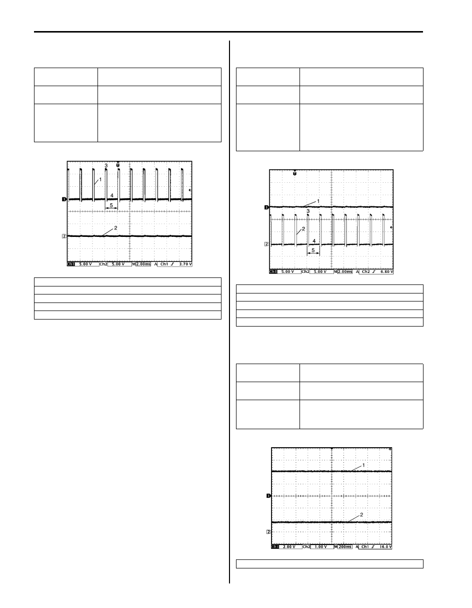
Reference waveform No.22
Throttle actuator output signal with ignition switch turned 
ON

Reference waveform No.23
Throttle actuator output signal with ignition switch turned 
ON

Reference waveform No.24
Manifold absolute pressure sensor signal (1) with 
ignition switch turned ON

Measurement 
terminal

CH1: “C37-45” to “C37-58”
CH2: “C37-44” to “C37-58”

Oscilloscope 
setting

CH1: 5 V/DIV, CH2: 5 V/DIV
TIME: 2 ms/DIV

Measurement 
condition

• After warmed up to normal 

operating temperature

• Ignition switch turned ON and 

accelerator pedal at idle position

1. Throttle actuator drive signal (“C37-45” terminal)
2. Throttle actuator drive signal (“C37-44” terminal)
3. ON signal
4. OFF signal
5. One duty cycle

I4RS0B110081-02

Measurement 
terminal

CH1: “C37-45” to “C37-58”
CH2: “C37-44” to “C37-58”

Oscilloscope 
setting

CH1: 5 V/DIV, CH2: 5 V/DIV
TIME: 2 ms/DIV

Measurement 
condition

• After warmed up to normal 

operating temperature

• Ignition switch turned ON and 

accelerator pedal at full 
depressed position

1. Throttle actuator drive signal (“C37-45” terminal)
2. Throttle actuator drive signal (“C37-44” terminal)
3. ON signal
4. OFF signal
5. One duty cycle

Measurement 
terminal

CH1: “C37-55” to “C37-57”
CH2: “C37-54” to “C37-41”

Oscilloscope 
setting

CH1: 2 V/DIV, CH2: 1 V/DIV
TIME: 200 ms/DIV

Measurement 
condition

• After warmed up to normal 

operating temperature

• Ignition switch turned ON

2. Throttle position sensor (main) signal

I4RS0B110082-02

I4RS0B110070-01

Engine General Information and Diagnosis: For Petrol Engine Model 1A-240

Reference waveform No.25
Manifold absolute pressure sensor signal (1) with engine 
racing

Reference waveform No.26
Knock sensor signal at engine speed 4000 r/min.

Reference waveform No.27
Knock sensor signal at engine speed 4000 r/min.

Reference waveform No.28
Oil control valve signal with engine idling (M16A engine)

Measurement 
terminal

CH1: “C37-55” to “C37-57”
CH2: “C37-54” to “C37-41”

Oscilloscope 
setting

CH1: 2 V/DIV, CH2: 2 V/DIV
TIME: 200 ms/DIV

Measurement 
condition

• After warmed up to normal 

operating temperature

• Engine racing

2. Throttle position sensor (main) signal
3. Racing
4. Idle

Measurement 
terminal

CH1: “C37-56” to “C37-58”

Oscilloscope 
setting

CH1: 1 V/DIV
TIME: 10 ms/DIV

Measurement 
condition

• After warmed up to normal 

operating temperature

• Run engine at 4000 r/min.

I5JB0A110093-01

I4RS0B110072-01

Measurement 
terminal

CH1: “C37-56” to “C37-58”

Oscilloscope 
setting

CH1: 1 V/DIV
TIME: 200 

µs/DIV

Measurement 
condition

• After warmed up to normal 

operating temperature

• Run engine at 4000 r/min.

Measurement 
terminal

CH1: “C37-60” to “C37-59”

Oscilloscope 
setting

CH1: 5 V/DIV
TIME: 2 ms/DIV

Measurement 
condition

At the moment of the ignition switch 
turned on

1. ON signal
2. OFF signal
3. Only duty cycle

I4RS0B110073-01

I4RS0B110074-01

1A-241 Engine General Information and Diagnosis: For Petrol Engine Model

Reference waveform No.29
Oil control valve signal with engine racing (M16A engine)

Reference waveform No.30
CAN communication line signal with ignition switch 
turned ON

Reference waveform No.31
Ignition coil signal and fuel injector signal with engine 
cranking

Measurement 
terminal

CH1: “C37-60” to “C37-59”

Oscilloscope 
setting

CH1: 5 V/DIV
TIME: 400 

µs/DIV

Measurement 
condition

• After warmed up to normal 

operating temperature

• Drive vehicle at 20 km/h (12 mph) 

and depress accelerator pedal 
fully

1. Accelerator pedal depressed fully
2. Accelerator pedal depressed partially
3. Oil control valve signal
4. ON signal
5. OFF signal

Measurement 
terminal

CH1: “E23-4” to “C37-58”
CH2: “E23-19” to “C37-58”

Oscilloscope 
setting

CH1: 1 V/DIV, CH2: 1 V/DIV
TIME: 40 

µs/DIV

Measurement 
condition

Ignition switch turned ON
(Signal pattern is depending on 
communication data)

1. CAN communication line signal (High)
2. CAN communication line signal (Low)

I4RS0B110075-01

I5JB0A110094-01

Measurement 
terminal

CH1: “C37-52” to “C37-58”
CH2: “C37-21” to “C37-58”
CH3: “C37-1” to “C37-58”
CH4: “C37-22” to “C37-58”

Oscilloscope 
setting

CH1: 5 V/DIV, CH2: 5 V/DIV
CH3: 50 V/DIV, CH4: 10 V/DIV
TIME: 200 ms/DIV

Measurement 
condition

• After warmed up to normal 

operating temperature

• Engine at cranking

[A]: J20A engine
[B]: M16A engine

1. Cylinder reference signal (CMP reference signal)
2. Ignition coil signal
3. No.1 fuel injector signal
4. Engine start signal

I5JB0A110095-01

Engine General Information and Diagnosis: For Petrol Engine Model 1A-242

Resistance Check

1) Remove ECM from its bracket referring to “Engine Control Module (ECM) Removal and Installation: For Petrol 

Engine Model in Section 1C”.

CAUTION

!


Never touch terminals of ECM itself or connect voltmeter or ohmmeter (2).


2) Connect special tool to ECM connectors securely.

NOTE
Do not connect the other connector of special tool to ECM.


3) Check resistance between each pair of terminals of disconnected connectors (1) as listed in the following table.

CAUTION

!


• Be sure to connect ohmmeter probe from wire harness side of coupler.
• Be sure to turn OFF ignition switch for this check.
• Resistance in the following table represents that measured when parts temperature is 20 

°C (68 °F).


1

2

I4RS0A110086-02

Terminals

Circuit

Standard resistance

Condition

E23-60 to E23-29

Main relay

160 – 240 

Battery disconnected 
and ignition switch 
turned ON

E23-15 to E23-29

Fuel pump relay

160 – 240 

C37-16 to E23-1/16 No.3 fuel injector

10.8 – 18.2 

C37-17 to E23-1/16 No.4 fuel injector

C37-5 to E23-1/16 EGR valve (stepping motor No.1 coil)

20 – 31 

C37-13 to E23-1/16 EVAP canister purge valve

28 – 35 

C37-2 to E23-1/16 No.2 fuel injector

10.8 – 18.2 

C37-6 to E23-1/16 EGR valve (stepping motor No.2 coil)

20 – 31 

C37-3 to E23-1/16 EGR valve (stepping motor No.4 coil)
C37-4 to E23-1/16 EGR valve (stepping motor No.3 coil)
C37-1 to E23-1/16 No.1 fuel injector

10.8 – 18.2 

C37-33 to E23-1/16 Intake manifold tuning vacuum solenoid valve

33 – 45 

C37-60 to C37-59

Oil control valve (M16A engine)

6 – 15 

E23-50 to E23-1/16 Throttle actuator control relay

160 – 240 


Content   ..  71  72  73  74   ..