Suzuki Grand Vitara JB627. Manual - part 298
8B-18 Air Bag System:
Scan Tool Data
S6JB0B8204006
Data list of SDM
Scan Tool Data Definition
Back Up Volt (V): This parameter indicates the
capacity of the backup condenser installed to
maintain the ignition current (as much as possible)
even when the power supply to SDM that ignites the
inflator is shut off.
Battery Volt (V): Battery voltage is an analog input
signal read by SDM.
System ID (4ch/8ch): This parameter indicates the
number of initiator circuits.
Driv A/B Ini Res (Driver air bag initiator resistance)
(ohm): This parameter indicates the resistance of
the driver air bag initiator circuit.
Pass A/B Ini Res (Passenger air bag initiator
resistance) (ohm): This parameter indicates the
resistance of the passenger air bag initiator circuit.
Driv Pret Ini Res (Driver pretensioner initiator
resistance) (ohm): This parameter indicates the
resistance of the driver seat belt pretensioner
initiator circuit.
Pass Pret Ini Res (Passenger pretensioner initiator
resistance) (ohm): This parameter indicates the
resistance of the passenger seat belt pretensioner
initiator circuit.
LH Side Ini Res (Left side-air bag initiator resistance)
(ohm): This parameter indicates the resistance of
the left side-air bag initiator circuit.
RH Side Ini Res (Right side-air bag initiator
resistance) (ohm): This parameter indicates the
resistance of the right side-air bag initiator circuit.
LH Curtain Ini Res (Left side curtain-air bag initiator
resistance) (ohm): This parameter indicates the
resistance of the left side curtain-air bag initiator
circuit.
RH Curtain Ini Res (Right side curtain-air bag
initiator resistance) (ohm): This parameter
indicates the resistance of the right side curtain-air
bag initiator circuit.
“AIR BAG” Warning Light Comes ON Steady
S6JB0B8204007
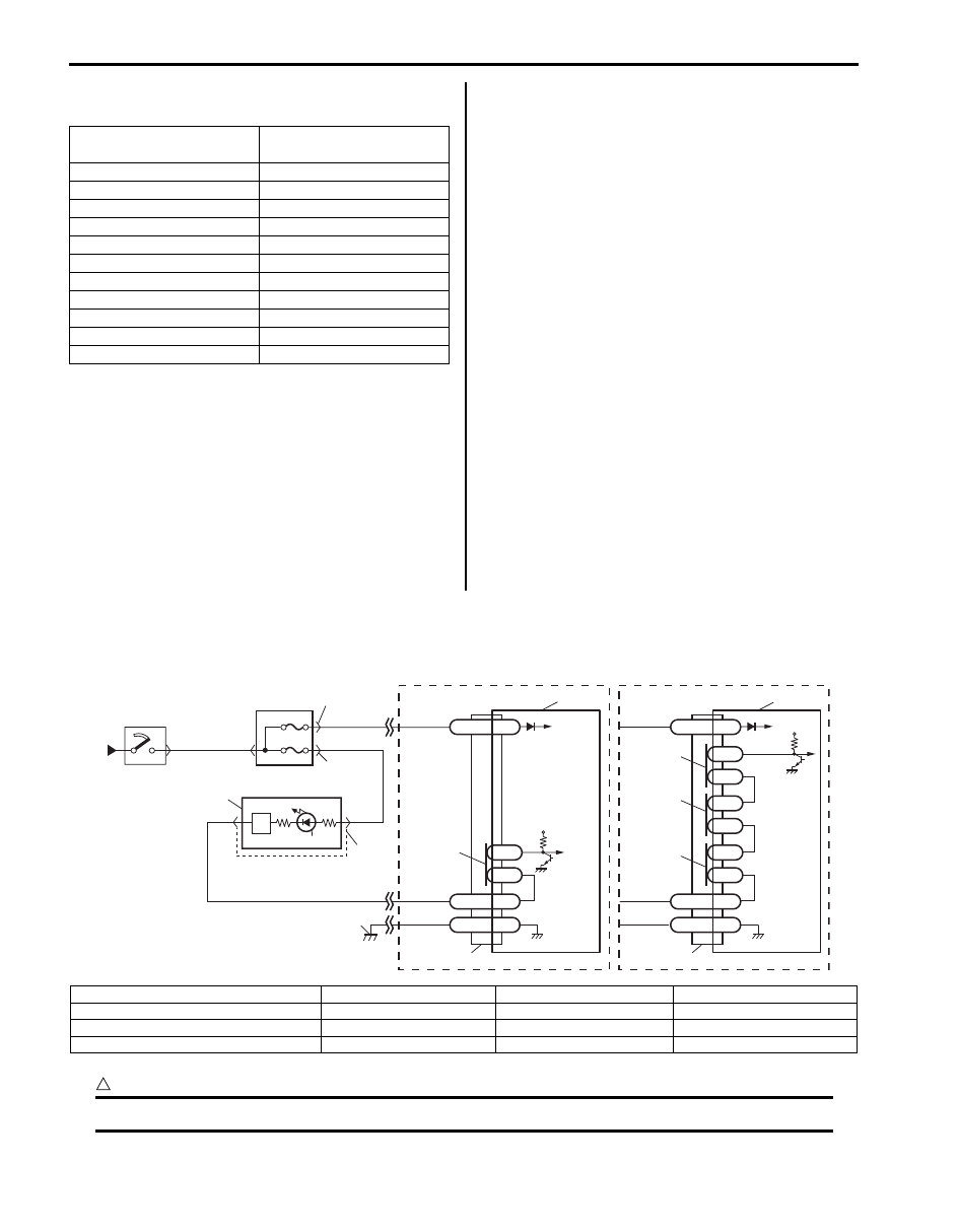
Wiring Diagram
CAUTION
!
Be sure to observe instructions under CAUTION in “Air Bag Diagnostic System Check Flow”.
Scan Tool Data
Normal Condition /
Reference Value
Battery volt
10 – 14 V
Back up volt
27.0 – 33.0 V
System ID
4ch or 8ch
Driv A/B Ini Res
2.1 – 3.8 ohm
Pass A/B Ini Res
1.8 – 2.8 ohm
Driv Pret Ini Res
1.8 – 2.9 ohm
Pass Pret Ini Res
1.8 – 2.9 ohm
LH Side Ini Res
1.8 – 2.6 ohm
RH Side Ini Res
1.8 – 2.6 ohm
LH Curtain Ini Res
1.8 – 2.8 ohm
RH Curtain Ini Res
1.8 – 2.8 ohm
BLK
G47-18
G47-20
L2
L1
GND
WL
“G47”
12V
1
2
6
8
4
5
RED
PPL/RED
BLK/YEL
YEL/BLK
BLK
RED
YEL/BLK
“G01”
7
“G28”
“G03”
G47-16
IG
[A]
G46-7
G46-16
L2
L1
GND
WL
“G46”
L4
L3
12V
G46-11
IG
[B]
L6
L5
3
10
10
9
9
9
9
11
I5JB0A820017-01
[A]: Without side-air bag and curtain-air bag
3. Junction block assembly
7. Light driver
11. Ground for air bag system
[B]: With side-air bag and curtain-air bag
4. “A/B” fuse
8. “AIR BAG” warning light
1. From main fuse
5. “METER” fuse
9. Connection detection pin
2. Ignition switch
6. Combination meter
10. SDM