Suzuki Grand Vitara JB627. Manual - part 297
 

  Index      Suzuki     Suzuki Grand Vitara JB627 - service repair manual


Search            


Content   ..  295  296  297  298   ..


Suzuki Grand Vitara JB627. Manual - part 297


8B-14 Air Bag System: 

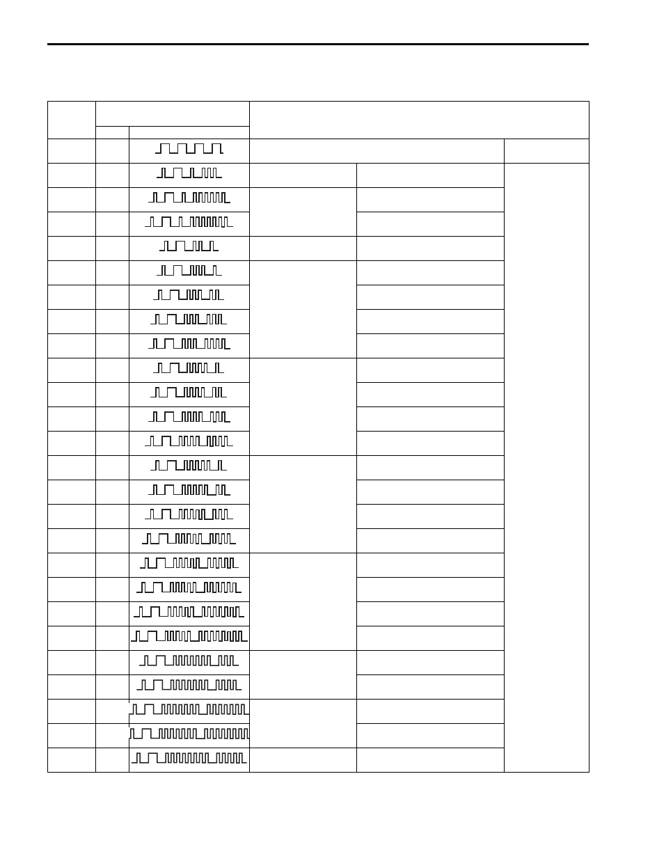
DTC Table

S6JB0B8204003

SDM DTC

DTC

“AIR BAG” warning light 

flashing pattern

Diagnosis

No.

Mode

0000

Normal

)

 B1013 1013

SDM

SDM fault

Diagnose trouble 
according to 
diagnostic flow 
corresponding to 
each code No.

)

 B1016 1016

Power source voltage

Too high

)

 B1017 1017

Too Low

)

 B1021 1021

SDM

Air bag module exploded

)

 B1031 1031

Driver air bag circuit

Resistance high

)

 B1032 1032

Resistance low

)

 B1033 1033

Short to ground

)

 B1034 1034

Short to power circuit

)

 B1041 1041

Passenger air bag 
circuit

Resistance high

)

 B1042 1042

Resistance low

)

 B1043 1043

Short to ground

)

 B1044 1044

Short to power circuit

)

 B1051 1051

Driver pretensioner 
circuit

Resistance high

)

 B1052 1052

Resistance low

)

 B1053 1053

Short to ground

)

 B1054 1054

Short to power circuit

)

 B1055 1055

Passenger 
pretensioner circuit

Resistance high

)

 B1056 1056

Resistance low

)

 B1057 1057

Short to ground

)

 B1058 1058

Short to power circuit

)

 B1073 1073

Driver forward-sensor 
circuit

Short to ground

)

 B1074 1074

Short to power circuit or open

)

 B1077 1077

Passenger forward-
sensor circuit

Short to ground

)

 B1078 1078

Short to power circuit or open

)

 B1085 1085

Side-sensor

Wrong assembly

MCODEB0000-0-01

MCODEB1013-0-01

MCODEB1016-0-01

MCODEB1017-0-01

MCODEB1021-0-01

MCODEB1031-0-01

MCODEB1032-0-01

MCODEB1033-0-01

MCODEB1034-0-01

MCODEB1041-0-01

MCODEB1042-0-01

MCODEB1043-0-01

MCODEB1044-0-01

MCODEB1051-0-01

MCODEB1052-0-01

MCODEB1053-0-01

MCODEB1054-0-01

MCODEB1055-0-01

MCODEB1056-0-01

MCODEB1057-0-01

MCODEB1058-0-01

MCODEB1073-0-01

MCODEB1074-0-01

MCODEB1077-0-01

MCODEB1078-0-01

MCODEB1085-0-01

Air Bag System:  8B-15

)

 B1086 1086

Left side-sensor

Performance problem

Diagnose trouble 
according to 
diagnostic flow 
corresponding to 
each code No.

)

 B1087 1087

Communication error

)

 B1096 1096

Right side-sensor

Performance problem

)

 B1097 1097

Communication error

)

 B1321 1321

Left side-air bag

Resistance high

)

 B1322 1322

Resistance low

)

 B1323 1323

Short to ground

)

 B1324 1324

Short to power circuit

)

 B1325 1325

Right side-air bag

Resistance high

)

 B1326 1326

Resistance low

)

 B1327 1327

Short to ground

)

 B1328 1328

Short to power circuit

)

 B1331 1331

Left side curtain-air 
bag circuit

Resistance high

)

 B1332 1332

Resistance low

)

 B1333 1333

Short to ground

)

 B1334 1334

Short to power circuit

)

 B1335 1335

Right side curtain-air 
bag circuit

Resistance high

)

 B1336 1336

Resistance low

)

 B1337 1337

Short to ground

)

 B1338 1338

Short to power circuit

DTC

“AIR BAG” warning light 

flashing pattern

Diagnosis

No.

Mode

MCODEB1086-0-01

MCODEB1087-0-01

MCODEB1096-0-01

MCODEB1097-0-01

MCODEB1321-0-01

MCODEB1322-0-01

MCODEB1323-0-01

MCODEB1324-0-01

MCODEB1325-0-01

MCODEB1326-0-01

MCODEB1327-0-01

MCODEB1328-0-01

MCODEB1331-0-01

MCODEB1332-0-01

MCODEB1333-0-01

MCODEB1334-0-01

MCODEB1335-0-01

MCODEB1336-0-01

MCODEB1337-0-01

MCODEB1338-0-01

8B-16 Air Bag System: 

DTC Check

S6JB0B8204004

Using SUZUKI Scan Tool

1) Turn ignition switch to OFF position.
2) Connect SUZUKI scan tool to data link connector 

(DLC) located on underside of instrument panel at 
driver’s seat side.

Special tool
(A):  SUZUKI scan tool

3) Turn ignition switch to ON position.
4) Read DTC according to instructions displayed on 

SUZUKI scan tool and print it or write it down. Refer 
to SUZUKI scan tool operator’s manual for further 
details.
If communication between scan tool and SDM is not 
possible, check if scan tool is communicable by 
connecting it to SDM in another vehicle. If 
communication is possible in this case, scan tool is 
in good condition. Then check data link connector 
and serial data line (circuit) in the vehicle with which 
communication was not possible.

5) After completing the check, turn ignition switch to 

OFF position and disconnect SUZUKI scan tool from 
data link connector (DLC) (1).

Using Monitor Connector (If Equipped)

1) Using service wire (3), ground diagnosis switch 

terminal (2) in “AIR BAG” monitor coupler (1).

2) Read DTC from flashing pattern of malfunction 

indicator lamp (“AIR BAG” warning light) Referring to 
“DTC Table”.
If light does not indicate DTC, proceed to ““AIR BAG” 
Warning Light Cannot Indicate Flashing Pattern of 
DTC (If Equipped with “AIR BAG” Monitor Coupler)”.

3) After completing the check, turn ignition switch to 

OFF position and disconnect service wire from “AIR 
BAG” monitor coupler.

Example: When driver air bag initiator circuit resistance high (DTC B1031) is set

(A)

1

I5JB0A820013-01

4. Body ground

1

3

4

1

2

I5JB0A820014-02

DTC B1031

A

B

1

1

3

0

0.3

0.3

0.3

1.0 1.0

1.0

1.0

3.0

3.0

C

D

C

C

C

I5JB0A820015-01

A: “AIR BAG” warning light is turned ON

C: Code No.1031 

B: “AIR BAG” warning light is turned OFF

D: Time (sec.)

Air Bag System:  8B-17

DTC Clearance

S6JB0B8204005

Using SUZUKI Scan Tool

1) Turn ignition switch to OFF position.
2) Connect SUZUKI scan tool to data link connector 

(DLC) (1) in the same manner as when making this 
connection for DTC check.

Special tool
(A):  SUZUKI scan tool

3) Turn ignition switch to ON position.
4) Erase DTC according to instructions displayed on 

SUZUKI scan tool. Refer to SUZUKI scan tool 
operator’s manual for further details.

5) After completing the clearance, perform “DTC 

Check” and confirm that normal DTC (NO CODES) 
is displayed and not malfunction DTC.

6) Turn ignition switch to OFF position and disconnect 

SUZUKI scan tool from DLC.

NOTE
If DTC B1013 or B1021 is stored in SDM, it is 
not possible to clear DTC.


Using Monitor Connector (If Equipped)

1) Turn ignition switch to ON position and wait about 6 

seconds or more.

2) Using service wire (4), repeat shorting and opening 

between diagnosis switch terminal (3) on “AIR BAG” 
monitor coupler (1) and body ground (2) 5 times at 
about 1 second intervals within 10 seconds.

3) Perform “DTC Check” and confirm that normal DTC 

(NO. 0000) is displayed and not malfunction DTC.

NOTE
If DTC B1013 or B1021 is stored in SDM, it is 
not possible to clear all DTC.


(A)

1

I5JB0A820013-01

O: Open

T: Max, 10 seconds

S: Short

T1: About 1 sec.

O

S

T

T1 T1

1

3

2

4

5

2

4

1

3

1

I5JB0A820016-01


Content   ..  295  296  297  298   ..