Suzuki Grand Vitara JB627. Manual - part 295
 

  Index      Suzuki     Suzuki Grand Vitara JB627 - service repair manual


Search            


Content   ..  293  294  295  296   ..


Suzuki Grand Vitara JB627. Manual - part 295


8B-6 Air Bag System: 

General Description

Air Bag System Construction

S6JB0B8201001

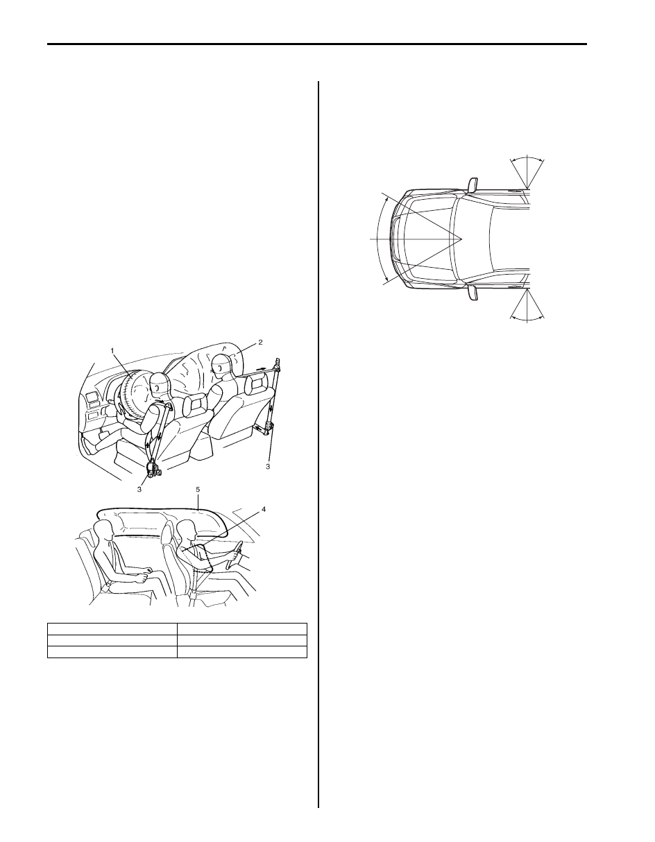
With the air bag system which includes front air bags, 
side curtain-air bag and side-air bags for both the 
driver’s and passenger’s sides as well as the seat belt 
pretensioners, the sag of the seat belt is taken up (for 
seat belt with pretensioner), the driver air bag (inflator) 
module is deployed from the center of the steering 
column and the passenger air bag (inflator) module from 
the top of the instrument panel in front of the front 
passenger seat in occurrence of a front collision with an 
impact larger than a certain set value to supplement 
protection offered by the driver and front passenger seat 
belts.
Side-air bag (inflator) module is deployed from the side 
of the seat back in occurrence of a sideward collision 
with an impact larger than a certain set value.
Side curtain-air bag (inflator) module is deployed from 
the roof side in occurrence of a sideward collision with 
an impact larger than a certain set value.

The air bag system is designed to activate only in severe 
frontal and sideward collisions. It is not designed to 
activate in rear impacts, rollovers, or minor frontal and 
sideward collisions, since it would offer no protection in 
those types of accidents.

1. Driver air bag

4. Side-air bag

2. Passenger air bag

5. Side curtain-air bag

3. Seat belt pretensioner

I4RS0B820002-02

I5JB0A820007-01

Air Bag System:  8B-7

Air Bag System Input / Output Table

S6JB0B8201002

There are two types of air bag system of this model
• Consisting of 4 items, i.e., air bags for driver and front passenger and seat belts with pretensioner for driver and 

front passenger sides

• Consisting of 8 items, i.e., air bags for driver and front passenger, seat belts with pretensioner for driver and front 

passenger sides, side-air bags for driver and front passenger and curtain-air bags for driver and front passenger 
sides
The side-air bag and curtain-air bag on the same side deploy at the same time only when an impact is applied to 
that side. For the details, refer to the table below.

INPUT

Sensor in SDM and
forward-sensor

Driver side-air bag 
and Driver side 
curtain-air bag

Passenger side-air bag 
and Passenger side
curtain-air bag

Driver side-sensor

Passenger side-sensor

OUTPUT

Signal from

sensor

Driver air bag, Passenger
air bag, Seat belt with
pretensioner (LH) and Seat
belt with pretensioner (RH)

I4RS0A820005-01

8B-8 Air Bag System: 

Schematic and Routing Diagram

Air Bag System Wiring Circuit Diagram

S6JB0B8202001

Air bag system without side-air bag and curtain-air bag

Terminal arrangement of SDM (viewed from harness side)

Connector “G47” (SDM connector)

GRN/ORN

GRN/YEL

BLU/ORN

BLU/YEL

GRN/ORN

GRN/YEL

BLU/ORN

BLU/YEL

12V

5V

5V

YEL

ORN

PNK/BLK

ORN

PNK/BLK

PPL/WHT

“E77”

“G06”

“L36”

“E24”

“E13”

PPL

BLK

“G34”

G47-18

G47-16

G47-22

G47-13

G47-4

G47-8

G47-7

G47-1

G47-2

G47-14

G47-20

L2

L1

ADS

IG

ST

G47-9 FD+

G47-17 FD-

DNS

GND

WL

PP-

PP+

DP-

DP+

“L12”

“G55” “L29”

“G47”

“G47”

12V

1

2

6

8

4

5

RED

PPL/RED

BLK/YEL

YEL/BLK

“G01”

7

“G28”

“G03”

PNK

PNK/BLU

PNK

PNK/BLU

G47-11 FP+

G47-19 FP-

[C]

[D]

“E13”      “E77”, “G01”      “G68”, “L12”      “L36” and “Q01”

G47-3

G47-5

G47-6

GRN/RED

GRN

BLU/RED

YEL/RED

BLU/RED

YEL/RED

“G65”

[B] “G27”

[A] “G26”

“G68”

“G67”

“Q01”

D1+

D1-

P1+

P1-

3

10

12

11

13

14

16

9

22

15

17

18

19

20

21

I5JB0A820008-01

[A]: For vehicle without cruise control system

6. Combination meter

15. Ground for air bag system

[B]: For vehicle with cruise control system

7. Light driver

16. SDM

[C]: Shorting bar

8. “AIR BAG” warning light

17. Contact coil

[D]: Connector

9. Connection detection pin

18. Driver air bag (inflator) module

1. To battery

10. To BCM

19. Passenger air bag (inflator) module

2. Ignition switch

11. To data link connector (DLC)

20. Driver seat belt pretensioner

3. Junction block assembly

12. To ECM, TCM, BCM, ABS hydraulic unit / control 

module assembly and 4WD control module

21. Passenger seat belt pretensioner

4. “A/B” fuse

13. Driver forward-sensor

22. “AIR BAG” monitor coupler (if equipped)

5. “METER” fuse

14. Passenger forward-sensor

1. SDM connector “G47”

Terminal

Terminal 

symbol

Circuit

Terminal

Terminal 

symbol

Circuit

G47-1

PP+

Passenger seat belt pretensioner (+) G47-13

ST

DLC

G47-2

PP–

Passenger seat belt pretensioner (–) G47-14

DNS

Diagnosis switch

G47-3

P1+

Passenger air bag (+)

G47-15

G47-4

P1–

Passenger air bag (–)

G47-16

IG

Ignition switch (power source)

L1

L2

1

2

3

4

5

6

7

8

9

10

11

12

13

14

15

16

17

18

19

20

21

22

23

1

I5JB0A820009-01

Air Bag System:  8B-9

Air bag system with side-air bag and curtain-air bag

G47-5

D1–

Driver air bag (–)

G47-17

FD–

Driver forward-sensor (–)

G47-6

D1+

Driver air bag (+)

G47-18

WL

“AIR BAG” warning light

G47-7

DP–

Driver seat belt pretensioner (–)

G47-19

FP–

Passenger forward-sensor (–)

G47-8

DP+

Driver seat belt pretensioner (+)

G47-20

GND

Ground

G47-9

FD+

Driver forward-sensor (+)

G47-21

G47-10

G47-22

ADS

Air bag deployed signal for BCM

G47-11

FP+

Passenger forward-sensor (+)

G47-23

G47-12

Terminal

Terminal 

symbol

Circuit

Terminal

Terminal 

symbol

Circuit

PPL

“G34”

1

2

5

RED

PPL/RED

BLK/YEL

YEL/BLK

GRN/ORN

GRN/YEL

BLU/ORN

BLU/YEL

12V

5V

YEL

ORN

PNK/BLK

ORN

PNK/BLK

PPL/WHT

“E79”

“L36”

“L12”

BLK

G46-7

G46-11

G46-15

G46-9

G46-6

L33-5

L33-6

L33-8

L33-7

G46-16

L6

L5

L4

L3

L2

L1

ADS

IG

ST

G46-12 DNS

FD+

FD-

L33-9

FP+

L33-10

FP-

GND

WL

PP-

PP+

DP-

DP+

“G03”

GRY/RED

GRY

BRN/WHT

BRN

“L25”

“L30”

L33-1

L33-2

L33-4

L33-3

RS-

RS+

LS-

LS+

YEL/GRN

YEL/BLU

BLK/YEL

BRN/YEL

“G18”

“G41”

L32-1

L32-2

L32-4

L32-3

RC-

RC+

LC-

LC+

12V

“L03”

WHT/RED

LT GRN/BLK

WHT/GRN

LT GRN

L33-13 SL+

L33-14 SL-

L33-16 SR+

L33-15 SR-

“G01”

“G28”

“E24”

“E13”

“L11”

“L35”

6

8

7

PNK

PNK/BLU

PNK

PNK/BLU

L33-12

L33-11

GRN/RED

GRN

BLU/RED

YEL/RED

BLU/RED

YEL/RED

“G65”

“G67” “G68”

“Q01”

[C]

[D]

“E13”      “E79”, “G01”      “G68”, “L12”      “L36” and “Q01”      “Q03”

G46-5

G46-2

G46-1

D1+

D1-

P1+

P1-

BLU

BLU

BLK

BLK

[B] “G27”

[A] “G26”

5V

3

4

9

9

9

10

11

12

28

13

14

15

16

17

18

19

20

21

22

23

24

25

“Q03”

“Q02”

26

27

I5JB0A820010-01

[A]: For vehicle without cruise control system

8. “AIR BAG” warning light

19. Contact coil

[B]: For vehicle with cruise control system

9. Connection detection pin

20. Driver air bag (inflator) module

[C]: Shorting bar

10. To BCM

21. Passenger air bag (inflator) module

[D]: Connector

11. To data link connector (DLC)

22. Driver seat belt pretensioner

1. To battery

12. To ECM, TCM, BCM, ABS hydraulic unit / control 

module assembly and 4WD control module

23. Passenger seat belt pretensioner

2. Ignition switch

13. Ground for air bag system

24. Left side-air bag (inflator) module

3. Junction block assembly

14. Driver forward-sensor

25. Right side-air bag (inflator) module

4. “A/B” fuse

15. Passenger forward-sensor

26. Left side curtain-air bag (inflator) module


Content   ..  293  294  295  296   ..