Subaru Legacy (2023 year). Manual in english - page 19
 

  Index      Manuals     Subaru Legacy (2023 year). Manual in english


Search            copyright infringement  


Content      ..     17      18      19      20     ..


Subaru Legacy (2023 year). Manual in english - page 19


(294,1)

!

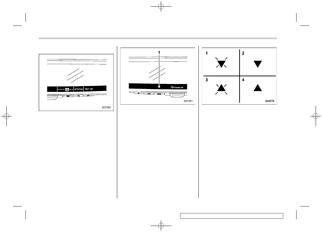
Using Two-Way Communication

Press any of the left, center or right buttons
to display the main menu. Select
HomeLink menu using the left button.
Select “STATUS” using the center button.

NOTE

The main menu cannot be displayed on
the display while the select lever is in a
position other than the “P” position.

1)

Status Indicators

Recall and display (at any time) the last
recorded garage door status message
communicated to HomeLink. HomeLink
will display the last recorded status for 5
seconds.

1)

Garage Door Opener CLOSING (Blinking
Orange)

2)

Garage Door Opener CLOSED (Solid
Green)

3)

Garage Door Opener OPENING (Blink-
ing Orange)

4)

Garage Door Opener OPENED (Solid
Green)

If two-way communication programming is
successful, HomeLink will display the
status of your garage door opener with
arrow indicators.

Mirrors

292

(295,1)

!

Certification

In the event that there are still program-
ming difficulties or questions, additional
HomeLink information and programming
videos can be found at
www.HomeLink.com/Subaru,
www.youtube.com/HomeLinkGentex, or
by calling the toll-free HomeLink-hotline
at 1-800-355-3515.

.

U.S.-spec. models

CAUTION

FCC WARNING

Changes or modifications not ex-
pressly approved by the party re-
sponsible for compliance could void
the user’s authority to operate the
equipment.

.

Canada-spec. models

– CONTINUED –

Mirrors

293

3

Instruments

and

Controls

(296,1)

HomeLink

®

and the HomeLink

®

house are

registered trademarks of Gentex Corpora-
tion.

WARNING

.

W h e n

p r o g r a m m i n g

t h e

HomeLink

®

Wireless Control Sys-

tem, you may be operating a
garage door opener or other
device. Make sure that people
and objects are out of the way of
the garage door or other device
to prevent potential harm or da-
mage.

.

Do not use the HomeLink

®

Wire-

less Control System with a gar-
age door opener that lacks the
safety stop and reverse feature
as required by applicable safety
standards. A garage door opener
which cannot detect an object,
signaling the door to stop and
reverse, does not meet these
safety standards. Using a garage
door opener without these fea-
tures increases risk of serious
injury or death. For more infor-
mation, consult the HomeLink

®

website at www.HomeLink.com/
Subaru or call 1-800-355-3515.

!

Language

Changes the language displayed in the
Smart Rearview Mirror.
1. Press any of the left, center or right
buttons to display the main menu. Select
“LANGUAGE” using the left button.
2. Select the language using the right
button and press the center button.

NOTE

The main menu cannot be displayed on
the display while the select lever is in a
position other than the “P” position.

Mirrors

294

(297,1)

&

Outside Mirrors

!

Convex mirror (passenger side)

WARNING

Objects look smaller in a convex
mirror and farther away than when
viewed in a flat mirror. Do not use the
convex mirror to judge the distance
of vehicles behind you when chan-
ging lanes. Use the inside mirror (or
glance backwards) to determine the
actual size and distance of objects
that you view in convex mirror.

CAUTION

Make sure to adjust the mirrors
before driving.

!

Remote control mirror switch

: Select side to adjust
: Direction control

The remote control mirrors operate when
the ignition switch is in the “ON” or “ACC”
position.
1. Turn the control switch to the side that
you want to adjust. “L” is for the left mirror,
“R” is for the right mirror.
2. Move the control switch in the direction
you want to move the mirror.
3. Return the control switch to the neutral
position to prevent unintentional opera-
tion.

NOTE

.

The mirrors can also be adjusted

manually.

For models with memory function:

.

The outside mirror can be adjusted

for approximately 45 seconds after the
following conditions are met.

– The ignition switch is turned to
the “OFF” position.
– The door is unlocked using the
access key fob.

.

The outside mirror angle can be

registered with button “1”, “2” or each
of the key fobs. For details, refer to
“Power driver’s seat with synchronized
outside mirrors memory function”

P34.

.

The outside mirror angle can also be

retrieved with the Driver Monitoring
System user information. To do so,
perform user registration in the Driver
Monitoring System settings. Refer to
“Driver Monitoring System”

P233.

!

Reverse tilt-down feature (if
equipped)

When backing the vehicle up, the right
and/or left outside mirrors will turn down-
ward automatically to provide better rear
visibility.
1.

Push the ignition switch to the ON

position.
2. Move the select lever to the R (Re-
verse) position.
3. The outside mirror angle moves down-

– CONTINUED –

Mirrors

295

3

Instruments

and

Controls

(298,1)

ward.

The outside mirror angle will return to its
original position when the following condi-
tion are met.

.

Approximately 9 seconds after the

select lever is moved to any position other
than R (Reverse).

.

The ignition switch is turned to the

“OFF” position.

.

The vehicle is running.

NOTE

.

The reverse tilt-down mirror angle

can be registered with button “1”, “2”
or each of the key fobs. For details,
refer to “Power driver’s seat with
synchronized outside mirrors memory
function”

P34.

.

The reverse tilt-down mirror angle

can also be retrieved with the Driver
Monitoring System user information.
To do so, perform user registration in
the Driver Monitoring System settings.
Refer to “Driver Monitoring System”

P233.

.

The operational/non-operational

setting can be changed by operating
the center information display. For de-
tails, refer to “Car settings”

P226.

.

The factory setting (default setting)

for this function is set as the front
passenger’s side mirror. The setting of

driver’s side mirror operation can be
changed by a SUBARU dealer. Contact
your SUBARU dealer for details.

CAUTION

Depress the brake pedal during the
reverse tilt-down mirror angle ad-
justment.

To adjust the reverse tilt-down mirror
angle, adjust the outside mirror using the
remote control mirror switch while the
reverse tilt-down operates. For details
about how to adjust the outside mirror
angle, refer to “Remote control mirror
switch”

P295.

Memory function:

The angle of the reverse tilt-down mirror
can be registered. Register the position
with button “1”, “2” or each of the access
key fobs and retrieve the position.
For details about registration or retrieval of
a position, refer to “Power driver’s seat
with synchronized outside mirrors memory
function”

P34.

NOTE

If the seat is moved forward or back-
ward 1.18 in (30 mm) or more, the
reverse tilt-down will move to the
factory default position or the last

position hold.

Hold last position function:

The angle of the reverse tilt-down mirror
can be set to the latest adjusted angle.
The hold last position function operates
when the following condition are met.

.

The memory function is not used.

.

The seat is moved forward or backward

1.18 in (30 mm) or more.

NOTE

.

The factory setting (default setting)

for this function is set as “non-opera-
tional”. This setting can be changed to
“operational” at SUBARU dealers. For
more details, contact a SUBARU dealer.

.

If the hold last position function

setting is “non-operation”, the reverse
tilt-down will move to the factory de-
fault position.

Mirrors

296

(299,1)

!

Power folding mirror switch (if
equipped)

The power folding mirror switch operates
when the ignition switch is in the “ON” or
“ACC” position.
To fold the outside mirrors, press the
power folding mirror switch. To unfold the
mirrors, press the switch again.

NOTE

.

If the outside mirrors have been

operated (folded or unfolded) manually,
when you turn the ignition switch from
the “LOCK”/“OFF” position to the
“ACC” or “ON” position, the outside
mirrors may be adjusted automatically
depending on the status of the power
folding mirror switch.

.

If the outside mirrors have been

manually folded slightly forward of the
regularly unfolded position, when you
turn the ignition switch from the
“LOCK”/“OFF” position to the “ACC”
or “ON” position, the outside mirrors
may automatically fold further forward
depending on the status of the power
folding mirror switch. When this hap-
pens, press the power folding mirror
switch. By doing so, the outside mir-
rors which have been folded to the
furthest forward position will extend to
the regularly unfolded position and
then fold rearward in the usual way. In
order to unfold the outside mirrors,
press the switch again.

.

When you fold the outside mirrors

manually, the mirrors may not unfold
when the switch is pressed, even
though the motor operating sound is
heard. When this happens, operate the
power folding mirror switch again.

.

When you unfold the outside mirrors

manually, the mirrors may become
wobbly. Be sure to unfold the mirrors
by operating the switch. If the outside
mirrors are still wobbly, fold the mirrors
again and then unfold them by operat-
ing the switch again.

.

When the temperature is low, the

outside mirrors may stop during opera-
tion. Push the switch again. When the

outside mirrors do not work by operat-
ing the switch, move the outside mir-
rors several times manually. This
makes it possible to operate them by
switch operation.

.

When you operate the power folding

mirror switch continuously, it may not
work. This is not a malfunction. Operate
after waiting for a short period of time.

.

The outside mirrors can be operated

(folded or unfolded) manually for ap-
proximately 45 seconds after the fol-
lowing conditions are met.

– The ignition switch is turned to
the “OFF” position.
– The door is unlocked using the
access key fob.

!

Power folding door mirror func-
tion (if equipped)

The mirrors are automatically folded when
the power folding mirror switch is in the
mirror unfolding position, the ignition
switch is turned OFF, and the doors are
locked.
The mirrors are automatically unfolded
when the power folding mirror switch is in
the mirror unfolding position and the doors
are unlocked.

– CONTINUED –

Mirrors

297

3

Instruments

and

Controls

(300,1)

NOTE

.

The power folding door mirror func-

tion does not operate when the power
folding mirror switch is in the mirror
unfolding position.

.

The setting of the power folding door

mirrors function can be changed by
operating the center information dis-
play. For details, refer to “Car settings”

P226. Also, the setting can be chan-

ged by your SUBARU dealer.
We recommend that you contact your
SUBARU dealer for details.

3-19. Tilt/Telescopic Steering
Wheel

WARNING

.

Do not adjust the steering wheel

tilt/telescopic position while driv-
ing. This may cause loss of
vehicle control and result in per-
sonal injury.

.

If the lever cannot be raised to the

fixed position, adjust the steering
wheel again. It is dangerous to
drive without locking the steering
wheel. This may cause loss of
vehicle control and result in per-
sonal injury.

1)

Tilt adjustment

2)

Telescopic adjustment

1. Adjust the seat position. Refer to “Front
Seats”

P28.

2. Pull the tilt/telescopic lock lever down.
3. Move the steering wheel to the desired
level.
4. Pull the lever up to lock the steering
wheel in place.
5. Make sure that the steering wheel is
securely locked by moving it up and down,
and forward and backward.

Tilt/Telescopic Steering Wheel

298

(301,1)

3-20. Heated Steering Wheel
System (If Equipped)

The Heated Steering Wheel system
warms the steering wheel at a constant
temperature.

1)

Heated Steering Wheel switch

2)

Indicator light

To turn on the Heated Steering Wheel
system, pull the Heated Steering Wheel
switch when the ignition switch is in the
“ACC” or “ON” position. Then the steering
wheel will be warmed and the indicator
light on the switch will illuminate. To turn off
the Heated Steering Wheel system, pull
the switch again. Then the indicator light
will turn off.

CAUTION

.

Use the Heated Steering Wheel

system with the engine running.
Otherwise, the battery voltage
may drop below the permissible
level and it may not be possible to
start the engine.

.

There is a possibility that people

with delicate skin may suffer
slight burns even at low tempera-
tures if they use the Heated
Steering Wheel for a long period
of time. When using the Heated
Steering Wheel, always be sure to
warn the persons concerned.

.

Do not cover the Heated Steering

Wheel with an object such as a
steering wheel cover. Doing so
may cause the Heated Steering
Wheel to overheat.

NOTE

.

If the surface temperature of the

steering wheel is approximately above
104

8

F (40

8

C) when the Heated Steering

Wheel system is turned on, the system
will not heat the steering wheel. Then,
the indicator light will continue to
illuminate.

.

The Heated Steering Wheel system

will automatically turn off approxi-
mately 30 minutes after the system
has been turned on.

Heated Steering Wheel System

299

3

Instruments

and

Controls

(302,1)

3-21. Horn

To sound the horn, push the horn pad.

Horn

300

(303,1)

4-1. Ventilator Control............................................ 302

Center Ventilators ............................................... 302
Side Ventilators .................................................. 302
Rear Ventilators (If Equipped) ............................. 302

4-2. Climate Control Panel .................................... 303

Dual 7.0-Inch Display Models .............................. 304
11.6-Inch Display Models .................................... 306

4-3. Automatic Climate Control Operation........... 308

Sensors.............................................................. 309

4-4. Manual Climate Control.................................. 310

Airflow Mode Selection ....................................... 310
Temperature Control ........................................... 311
Fan Speed Control.............................................. 312
Air Conditioner Control....................................... 312
Air Inlet Selection ............................................... 312
To Turn Off the Climate Control System .............. 313

4-5. Front Seat Heater and Ventilation

(If Equipped) .................................................. 313

Front Seat Heater ............................................... 313

Front Seat Ventilation ......................................... 314

4-6. Defrosting ........................................................314
4-7. Operating Tips for Heater and Air

Conditioner ....................................................315

Cleaning Ventilator Grille.................................... 315
Efficient Cooling after Parking in Direct

Sunlight ........................................................... 315

Lubrication Oil Circulation in the Refrigerant

Circuit.............................................................. 315

Checking Air Conditioning System before

Summer Season............................................... 315

Cooling and Dehumidifying in High Humidity

and Low Temperature Weather Condition ......... 316

Air Conditioner Compressor Shut-Off When

Engine Is Heavily Loaded ................................. 316

Refrigerant for Your Climate Control System ...... 316

4-8. Air Filtration System .......................................316

Replacing the Cabin Air Filter............................. 317

Climate Control

4

Climate

Control

(304,1)

4-1. Ventilator Control

&

Center Ventilators

Move the tabs to adjust the flow direction.
To close the ventilator, move the tab all the
way down.

&

Side Ventilators

1)

Open

2)

Close

Move the tab to adjust the flow direction.
To open the ventilator, turn the side grille
open/close wheel upward to the “ ”
position.
To close it, turn the wheel downward to the

” position.

&

Rear Ventilators (If Equipped)

1)

Open

2)

Close

Move the tab to adjust the flow direction.
To open the ventilator, turn the rear grille
open/close wheel upward to the “ ”
position.
To close it, turn the wheel downward to the

” position.

Ventilator Control

302

(305,1)

4-2. Climate Control Panel

WARNING

.

The cooling function operates

only when the engine is running.

.

Do not leave children or adults

who would normally require the
support of others alone in your
vehicle. Pets should not be left
alone either. On hot, sunny days,
temperatures in a closed vehicle
could quickly become high en-
ough to cause severe or possibly
fatal injuries to people or ani-
mals.

– CONTINUED –

Climate Control Panel

303

4

Climate

Control

(306,1)

&

Dual 7.0-Inch Display Models

1)

Defroster button (Refer to “Defrosting”

P314.)

2)

Rear window and outside mirror defogger
button (if equipped) (Refer to “Defogger
and Deicer”

P270.)

3)

Climate control screen (lower display)

4)

Temperature control button (Refer to
“Temperature Control”

P311.)

Climate Control Panel

304

(307,1)

!

Climate control screen

Climate control screen (lower display)

: Touch the climate control mode indicator

1)

Climate control ON/OFF icon

2)

Set temperature indicator

3)

Climate control mode indicator

4)

Customizable icon*

5)

Fan speed indicator

6)

Climate control mode select icon

7)

Airflow mode selection screen

*: The customizable icon can be changed to

the favorite icon. Refer to “General settings”

P239.

– CONTINUED –

Climate Control Panel

305

4

Climate

Control

(308,1)

&

11.6-Inch Display Models

1)

Climate control screen

2)

Rear window and outside mirror defogger
button (Refer to “Defogger and Deicer”

P270.)

3)

Passenger’s side temperature control
button (Refer to “Temperature Control”

P311.)

4)

Driver’s side temperature control button
(Refer to “Temperature Control”

P311.)

5)

Defroster button (Refer to “Defrosting”

P314.)

Climate Control Panel

306

(309,1)

!

Climate control screen

: Touch the climate control mode indicator

1)

Climate control mode indicator

2)

SYNC mode indicator

3)

Front passenger’s seat heater/ventilation
icon (if equipped)*

1

4)

Customizable icon*

2

5)

Fan speed control

6)

Climate control ON/OFF icon

7)

Driver’s seat heater/ventilation icon (if
equipped)*

1

8)

Climate control mode select icon

9)

Temperature control screen (passen-
ger’s side)

10) SYNC icon
11) Temperature control bar
12) Airflow mode selection screen
13) Temperature control screen (driver’s

side)

*1: For details, refer to “Front Seat Heater and

Ventilation”

P313.

*2: The customizable icon can be changed to

the favorite icon. Refer to “General set-
tings”

P221.

NOTE

The layout and the available functions
for operating the climate control screen
may vary depending on the number of
items shown on the Center Information
Display.

Climate Control Panel

307

4

Climate

Control


Content      ..     17      18      19      20     ..