Subaru Forester (2023 year). Manual in english - page 22
 

  Index      Manuals     Subaru Forester (2023 year). Manual in english


Search            copyright infringement  


Content      ..     20      21      22      23     ..


Subaru Forester (2023 year). Manual in english - page 22


(352,1)

.

When the airflow mode selection set to

” mode.

.

When the climate control system can
no longer maintain the set temperature.

.

When unbuckling the driver’s seatbelt

.

When opening the driver’s door

.

When activating the rear window de-
fogger

.

When the Auto Vehicle Hold function is
released, refer to “Auto Vehicle Hold
function”

P343.

!

Engine restart non-operational
conditions

WARNING

Do not open the engine hood when
the Auto Start Stop system is in
operation. It may cause the vehicle
to move while on a slope, the steer-
ing wheel operation may become
heavy, or the brakes may not work
well, which can create dangerous
conditions.

To ensure safety, the engine will not be
automatically restarted if the engine hood
is opened when the Auto Start Stop
system is in operation, even if the brake
pedal is released. In this case, check the
surrounding area and restart the engine by
normal operation.

Also, when the Auto Vehicle Hold opera-
tion indicator light is illuminated, the
engine will not restart.

NOTE

.

When the Auto Start Stop system is
in operation, the brake pedal may
feel stiff. However, this is not a
malfunction.

.

When the battery is discharged, the
engine will be automatically re-
started even if you keep the brake
pedal depressed.

.

In the following cases, the length of
time that the engine is temporarily
stopped by the Auto Start Stop
system may be shorter.

– When the climate control system

is in operation.

– When the outside temperature is

high, or when it is low (because
the climate control system can no
longer maintain the set tempera-
ture).

– When consumption of electricity

by electrical components is high.

.

When the engine is automatically
restarted by the Auto Start Stop
system, the power provided via the
accessory power outlet will be re-
duced. Depending on the connected
appliance, the power of the appli-

ance may temporarily turn off.

!

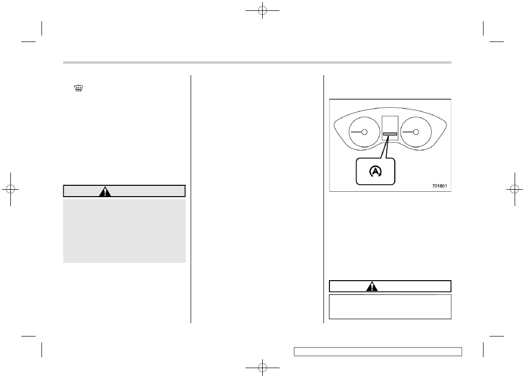
Auto Start Stop warning light

Auto Start Stop warning light (yellow)

The Auto Start Stop warning light will
illuminate in yellow when initially turning
the ignition switch to the “ON” position. The
light will turn off after the engine has
started.
The Auto Start Stop warning light will flash
when the Auto Start Stop system is
malfunctioning. We recommend that you
contact your authorized SUBARU dealer
for an inspection.

CAUTION

If the Auto Start Stop warning light
does not turn off after the engine has
started, the Auto Start Stop system

Auto Start Stop system

350

(353,1)

may be malfunctioning. We recom-
mend that you contact your author-
ized SUBARU dealer for an inspec-
tion.

!

Auto Start Stop OFF switch

Auto Start Stop OFF switch

Auto Start Stop OFF indicator light (yel-
low)

If the Auto Start Stop OFF switch is
pressed, operation of the Auto Start Stop
system will be disabled. The Auto Start
Stop OFF indicator light on the combina-
tion meter will then illuminate in yellow. If
the switch is pressed once more, the Auto
Start Stop system will turn on again. The
Auto Start Stop OFF indicator light will then
turn off.

While the engine is temporarily stopped by
the system, if the Auto Start Stop OFF
switch is pressed, the engine will be
restarted even if you do not release the
brake pedal.

NOTE

.

If the engine is restarted when the
Auto Start Stop system is not opera-
tional and the ignition switch has
been turned to the “LOCK”/“OFF”
position, the Auto Start Stop system
will turn on again.

.

Be sure to turn the ignition switch to
the “LOCK”/“OFF” position when
leaving the vehicle. Failure to do so
could result in the battery dischar-
ging.

!

Auto Start Stop No Activity Detected
indicator light

Auto Start Stop No Activity Detected
indicator light

If the operational conditions are not met
when the vehicle is stopped, the engine

– CONTINUED –

Auto Start Stop system

351

7

Starting

and

operating

(354,1)

will not stop and the Auto Start Stop No
Activity Detected indicator light will illumi-
nate. It will turn off when the vehicle begins
to drive.

&

Displaying the Auto Start
Stop system status

Approximate indications of the time that
the engine has been stopped by the Auto
Start Stop system and/or the amount of
fuel saved can be displayed on the
combination meter display (color LCD).
For details, refer to “Basic screens”

P193.

&

System warning

So that it can be used safely and comfor-
tably, the Auto Start Stop system is
designed to constantly monitor the vehicle
conditions as well as the environment
inside and outside the vehicle in addition
to driver operations, and to provide various
warnings to the driver via the warning light
and/or indicator light illuminating or flash-
ing and a buzzer sounding. For details
about the warning light and indicator light,
refer to “Auto Start Stop warning light/Auto
Start Stop OFF indicator light (yellow)”

P187.

!

Warning buzzer

The buzzer will sound when the engine
hood is opened while the engine is
stopped by the Auto Start Stop system.
When this occurs, the buzzer will stop
sounding when the following operations
are performed.

.

The engine is restarted by normal
operation. (Refer to “Preparing to drive”

P305.)

.

The ignition switch is turned to the
“LOCK”/“OFF” position.

!

Display of warning messages

If a warning message is displayed on the
combination meter display (color LCD)
while driving, a malfunction may have
occurred in the Auto Start Stop system.
In this case, the Auto Start Stop warning
light will illuminate or flash in yellow. We
recommend that you have your vehicle
inspected at a SUBARU dealer as soon as
possible.

7-18. Hill start assist system

WARNING

.

The Hill start assist system is a

device only for helping the driver
to START the vehicle on an uphill
grade. To prevent accidents
when the vehicle is parked on a
slope, be sure to firmly set the
parking brake. When setting the
parking brake, make sure that the
vehicle remains stationary when
the brake pedal is released.

.

Do not turn the ignition switch to

the “LOCK”/“OFF” position while
the Hill start assist system is
operating. The Hill start assist
system will be deactivated and
may lead to an accident.

The Hill start assist system is a device to
make the following vehicle operations
easier.

Hill start assist system

352

(355,1)

1

Starting forward facing uphill

2

Starting backward facing downhill

A

Brake pedal

When the vehicle has stopped with the
brake pedal depressed, the Hill start assist
system operates.

Braking power is maintained temporarily
(for approximately 2 seconds) by the Hill
start assist system after the brake pedal is
released. The driver is therefore able to
start the vehicle in the same way as on a
level grade, just using the accelerator
pedal.

If the braking power of the Hill start assist
system is insufficient after the brake pedal
is released, apply more braking power by
depressing the brake pedal again.

The Hill start assist system may not
operate on slight grades. Also, the Hill
start assist system does not operate in the
following cases.

.

When starting backward facing uphill

.

When starting forward facing downhill

.

While the parking brake is applied

.

While the ignition switch is in the “ACC”
or “LOCK”/“OFF” position

– CONTINUED –

Hill start assist system

353

7

Starting

and

operating

(356,1)

.

While the Vehicle Dynamics Control
warning light is illuminated. Refer to
“Vehicle Dynamics Control warning
light/Vehicle Dynamics Control opera-
tion indicator light”

P179.

.

While the Auto Start Stop warning light
is illuminated. Refer to “Auto Start Stop
warning light/Auto Start Stop OFF
indicator light (yellow)”

P187.

When using the Hill start assist system, a
braking effect may be felt even after the
brake pedal has been released.

CAUTION

The braking power of the Hill start
assist system may not be sufficient
when strong braking power is
needed (e.g., when towing a trailer).

NOTE

A slight jolt may be felt when the
vehicle begins to move forward after
being reversed.

7-19. BSD/RCTA (if equipped)

The BSD/RCTA consists of rear corner
radars with Blind Spot Detection and Rear
Cross Traffic Alert.

These functions enable the system to
detect objects or vehicles to the rear,
drawing attention to the driver when
changing a lane or when driving in reverse.

WARNING

The driver is responsible for driving
safely. Always be sure to check the
surroundings when changing lanes
or reversing the vehicle.

The system is designed to assist the
driver to change lanes or reverse
safely by monitoring the rear and
side areas of the vehicle. However,
you cannot rely on this system alone
in assuring the safety during a lane
change or reversing. Overconfi-
dence in this system could result in
an accident and lead to serious
injury or death. Since the system
operation has various limitations,
the flashing or illumination of the
BSD/RCTA approach indicator light
may be delayed or it may not operate
at all even when a vehicle is present

in a neighboring lane or approach-
ing from either side.

The driver is responsible for paying
attention to the rear and side areas
of the vehicle.

&

System features

BSD/RCTA consists of the following func-
tions.

.

To detect a vehicle in a blind spot on an
adjacent lane or a vehicle approaching
at high speeds (Blind Spot Detection).

.

To detect a vehicle approaching from
the right or left while reversing the
vehicle (Rear Cross Traffic Alert).

The system uses radar sensors for the
above functions.

NOTE

The BSD/RCTA radar sensor has been
certified by the radio wave related laws
of the U.S. and Canada. When driving in
other countries, certification of the
country where the vehicle is driven
must be obtained. For certification in
the U.S. and Canada, refer to “Certifica-
tion for the BSD/RCTA”

P362.

BSD/RCTA

354

(357,1)

!

Blind Spot Detection (BSD)

1

Operating range

The system warns the driver of dangers as
follows.

.

If the system detects a vehicle in the
blind spot, the BSD/RCTA approach
indicator light(s) on the outside mirror
(s) will illuminate.

BSD/RCTA approach indicator light

.

If the driver operates the turn signal
lever in the direction which the BSD/
RCTA approach indicator light is illumi-
nating, the corresponding BSD/RCTA
approach indicator light will flash.

!

Lane Change Assist (LCA)

1

Operating range

The system warns the driver of dangers as
follows.

.

If the system detects a vehicle ap-
proaching at a high speed in the
neighboring lanes, the BSD/RCTA ap-
proach indicator light(s) on the outside
mirror(s) will illuminate.

.

If the driver operates the turn signal
lever in the direction which the BSD/
RCTA approach indicator light is illumi-
nating, the corresponding BSD/RCTA
approach indicator light will flash.

– CONTINUED –

BSD/RCTA

355

7

Starting

and

operating

(358,1)

!

Rear Cross Traffic Alert (RCTA)

1

Operating range

The system notifies the driver of another
vehicle approaching from either side when
driving in reverse. This feature helps the
driver check the rear and side areas of the
vehicle when moving backward.

If the system detects a vehicle approach-
ing from either side while moving back-
ward, it warns the driver of dangers in the
following way.

.

The BSD/RCTA approach indicator
light(s) on the outside mirror(s) flashes.

.

A warning buzzer sounds.

.

An icon appears on the rear view
camera screen (audio/navigation moni-
tor)

!

Limitations of the detectability of
RCTA

Since the detectability of RCTA is limited,
the RCTA may not operate properly in
angled parking.

Example 1

1

The detection range of the radar sensors

2

Area out of detection range of the radar
sensors

A

Vehicle that may not be detected.

B

Parked vehicle

WARNING

An approaching vehicle (A) may not
be detected because the detection
range is limited by the parked vehi-
cle (B). Always be sure to check the
surroundings when reversing the

vehicle.

Example 2

1

The detection range of the radar sensors

C

Vehicle that may be detected.

NOTE

The system may detect that a vehicle
(C) is passing in front of your vehicle.
Always be sure to check the surround-
ings when reversing the vehicle.

BSD/RCTA

356

(359,1)

&

System operation

!

Operating conditions

The BSD/RCTA will operate when all of the
following conditions are met.

.

The ignition switch is in the “ON”
position.

.

The BSD/RCTA warning light and BSD/
RCTA OFF indicator light are turned off.

.

The EyeSight warning indicator is off.

.

The vehicle is driven at speeds above 7
mph (12 km/h) (except when rever-
sing).

.

The select lever is in the “R” position
(when reversing).

The BSD/RCTA will not operate in the
following situations.

.

The BSD/RCTA OFF indicator light is
on.

.

The vehicle speed is below 6 mph (10
km/h) even when the BSD/RCTA OFF
indicator light remains off (except when
reversing).

NOTE

.

In the following case, the BSD/RCTA
will stop operating and the BSD/
RCTA warning light will appear. If
the BSD/RCTA warning light ap-
pears, have your vehicle inspected
at a SUBARU dealer as soon as

possible.

– When a malfunction occurs in the

system, including the BSD/RCTA
approach indicator light.

.

In the following cases, the BSD/
RCTA will temporarily stop operat-
ing (or may stop operating) and the
BSD/RCTA OFF indicator light will
appear.

– When the radar sensor becomes

significantly misaligned (If the
orientation of the radar sensor is
shifted for any reason, readjust-
ment is required. Have the sensor
adjusted at a SUBARU dealer.)

– When a large amount of snow or

ice sticks to the rear bumper
surface around the radar sen-
sors.

– When the vehicle is driven on a

snow-covered road or in an en-
vironment in which there are no
objects around (such as in a
desert) for a long time.

– When the temperature around the

radar sensors increased exces-
sively due to long driving on
uphill grades in summer, etc.

– When the temperature around the

radar sensors becomes extre-
mely low.

– When the vehicle battery voltage

lowers.

– When an overvoltage occurs in

the vehicle battery.

When the above conditions are cor-
rected, the BSD/RCTA will resume
operation and the BSD/RCTA OFF
indicator light will disappear. How-
ever, if the BSD/RCTA OFF indicator
light has appeared for a prolonged
time, have the system inspected at a
SUBARU dealer as soon as possible.

.

The detectability of the radar sen-
sors is restricted. The BSD/RCTA
detection may be impaired and the
system may not operate properly
under the following conditions.

– When the rear bumper around the

radar sensors is distorted.

– When ice, snow or mud adheres

to the rear bumper surface
around the radar sensors.

– When stickers, etc. are affixed on

the areas of the radar sensors on
the rear bumper.

– During adverse weather condi-

tions such as rain, snow or fog

– When driving on wet roads such

a s s n o w - c o v e r e d r o a d s o r
through puddles

.

The radar sensors may not detect or
may have difficulty detecting the

– CONTINUED –

BSD/RCTA

357

7

Starting

and

operating

(360,1)

following.

– Small motorcycles, bicycles, pe-

destrians, stationary objects on
the road or road side, etc.

– Vehicles with body shapes that

the radar may not reflect (vehi-
cles with a low body height such
as sports cars or a trailer with no
cargo).

– Vehicles that are not approaching

your vehicle even though they
are in the detection area (either
on a neighboring lane to the rear
or beside your vehicle when
reversing). (The system deter-
mines the presence of approach-
ing vehicles based on data de-
tected by the radar sensors.)

– Vehicles traveling at significantly

different speeds

– Vehicles driving parallel to your

vehicle at almost the same speed
for a prolonged time

– Oncoming vehicles
– Vehicles in a lane beyond the

neighboring lane

– Vehicles travelling at a signifi-

cantly lower speed that you are
trying to overtake

.

On a road with extremely narrow
lanes, the system may detect vehi-
cles driving in a lane next to the

neighboring lane.

.

When the 8-inch audio/navigation
system is performing a software
update, the RCTA warning icons
may not be displayed on the audio/
navigation screen until the update is
complete.

&

BSD/RCTA approach indica-
tor light/warning buzzer

When the BSD/RCTA is active, the BSD/
RCTA approach indicator light will operate
to alert the driver when there are vehicles
in the neighboring lanes. When reversing
the vehicle, the BSD/RCTA approach
indicator light and warning buzzer will
operate to alert the driver that a vehicle is
approaching from the left or right side.

!

BSD/RCTA approach indicator light

BSD/RCTA approach indicator light

It is mounted in each side of the outside
mirrors.
The indicator light will illuminate when a
vehicle approaching from behind is de-
tected.
The indicator light will flash to warn the
driver of dangers under the following
conditions.

.

While the indicator light illuminates, if
you operate the turn signal lever toward
the side in which this light turned on.

.

When reversing the vehicle while the
system detects a vehicle approaching
from either side.

BSD/RCTA

358

(361,1)

!

BSD/RCTA approach indicator
light dimming function

When the headlights are turned on, the
brightness of the BSD/RCTA approach
indicator light will be reduced.

NOTE

.

You may have difficulty recognizing
the BSD/RCTA approach indicator
light under the following conditions.

– When affected by direct sunlight
– When affected by the headlight

beams from the vehicles behind

.

While the illumination brightness
control dial is in the fully upward
position, even if the headlights are
turned on, the brightness of the
BSD/RCTA approach indicator light
will not be reduced. For details about
the illumination brightness control
dial, refer to “Illumination bright-
ness control”

P165.

!

BSD/RCTA approach warning buz-
zer (only when reversing)

A warning buzzer sounds along with
flashing of the BSD/RCTA approach in-
dicator light to warn the driver of dangers.

The setting of the warning buzzer volume
can be changed by operating the combi-
nation meter display (color LCD). For

details, refer to “Menu screens”

P196.

!

Safety tips regarding the BSD/RCTA
approach indicator light/warning
buzzer

.

In the following cases, operation of the
BSD/RCTA approach indicator light
and the warning buzzer may be de-
layed or the system may fail to issue
these warnings.

– When a vehicle moves to the neigh-

boring lane from a lane next to the
neighboring lane.

– When driving on a steep incline or

on repeated sharp uphill and down-
hill grades

– When going beyond a pass
– When both your vehicle and a

vehicle driving on a neighboring
lane are driving on the far side of
each lane.

– When several narrowly-spaced ve-

hicles are approaching in a row.

– In low radius bends (tight bends or

when making turns at an intersec-
tion)

– When there is a difference in height

between your lane and the neigh-
boring lane.

– Immediately after the BSD/RCTA is

activated by pressing the BSD/
RCTA OFF switch.

– Immediately after the select lever is

shifted to the “R” position.

– When extremely heavy cargo is

loaded in the cargo area.

.

During reversing, operation of the BSD/
RCTA approach indicator light and the
warning buzzer may be delayed or the
system may fail to issue these warnings
under the following conditions.

– When backing out of an angled

parking space

– When a large-sized vehicle is

parked next to your vehicle. (That
vehicle prevents the propagation of
radar waves.)

– When reversing on sloped roads
– When reversing at a high speed

.

The BSD/RCTA approach indicator
light may illuminate when driving close

– CONTINUED –

BSD/RCTA

359

7

Starting

and

operating

(362,1)

to solid objects on the road or road side
(such as guardrails, tunnels or side-
walls).

.

The BSD/RCTA approach indicator
light may flash when turning at an
intersection in urban areas or a multi-
lane intersection.

.

The BSD/RCTA approach indicator
light may flash and the warning buzzer
may sound if a building or a wall exists
in the reversing direction.

.

In the following cases, the system may
detect a vehicle driving two lanes away
from your vehicle.

– When you are driving on the near

side of the lane of the corresponding
vehicle.

– When the vehicle driving two lanes

away is driving on the near side of its
lane from your vehicle.

&

BSD/RCTA OFF indicator
light

!

System temporary stop

1

BSD/RCTA temporary stop message

2

BSD/RCTA OFF indicator light

This display appears when the system is
used under the following conditions.

.

Extremely high or low temperatures

.

When abnormal voltage exists for the
vehicle battery.

.

When the radar sensor is significantly
misaligned.

Once the above conditions are corrected,
the system will recover from the temporary
stop condition and the indicator will dis-
appear. If the indicator remains displayed
for a prolonged time, have the system

inspected at a SUBARU dealer.

!

System temporary stop due to re-
duced radar sensitivity

1

BSD/RCTA temporary stop message due
to reduced radar sensitivity

2

BSD/RCTA OFF indicator light

This display appears when the detectabil-
ity of the radar sensors is reduced. Once
the condition is corrected, the system will
recover from the temporary stop condition
and the indicator will disappear. If the
indicator remains displayed for a pro-
longed time, have the system inspected
at a SUBARU dealer.

BSD/RCTA

360

(363,1)

&

BSD/RCTA warning light

!

System malfunction

1

BSD/RCTA malfunction message

2

At first, this message will appear

3

Then this message will appear

4

BSD/RCTA warning light

This display appears when a malfunction
occurs in the system. Contact a SUBARU
dealer and have the system inspected.

&

BSD/RCTA OFF switch

BSD/RCTA OFF switch

BSD/RCTA OFF indicator light

If the BSD/RCTA OFF switch is pressed,
the BSD/RCTA OFF indicator light ap-
pears on the combination meter, and the

BSD/RCTA is deactivated.
Press the switch again to activate the BSD/
RCTA. The BSD/RCTA OFF indicator light
will disappear.
When this occurs, the BSD/RCTA ap-
proach indicator light on the side of the
rearview mirror illuminates for a few
seconds and then turns off.

NOTE

.

In the following cases, the system
may not operate properly due to
blocked radar waves. Press the
BSD/RCTA OFF switch to deactivate
the system.

– When towing a trailer
– When a bicycle carrier or other

carrier item is fitted to the rear of
the vehicle.

– When using a chassis dynam-

ometer or free roller device, etc.

– When running the engine and

making the wheels rotate while
lifting up the vehicle

.

If the ignition switch is turned to the
“LOCK”/“OFF” position, the last
known status of the system is main-
tained. For example, if the ignition
switch is turned to the “LOCK”/
“OFF” position with the BSD/RCTA
deactivated, the BSD/RCTA will re-
main deactivated the next time the

– CONTINUED –

BSD/RCTA

361

7

Starting

and

operating

(364,1)

ignition switch is turned to the “ON”
position.

&

Certification for the BSD/
RCTA

!

U.S.-spec. models

FCC ID: OAYSRR3A

CAUTION

FCC WARNING

Changes or modifications not ex-
pressly approved by the party re-
sponsible for compliance could void
the user’s authority to operate the
equipment.

NOTE

This device complies with part 15 of the
FCC Rules. Operation is subject to the
following two conditions: (1) This de-
vice may not cause harmful interfer-
ence, and (2) this device must accept
any interference received, including
interference that may cause undesired
operation.

!

Canada-spec. models

BSD/RCTA

362

(365,1)

&

Handling of radar sensors

1

Sensors

The radar sensors, one on each side of the
vehicle, are mounted inside the rear
bumper.
To ensure correct operation of the BSD/
RCTA, observe the following precautions.

.

Always keep the bumper surface near
the radar sensors clean.

.

Do not affix any stickers or other items
on the bumper surface near the radar
sensors.

.

Do not modify the bumper near the
radar sensors.

.

Do not paint the bumper near the radar
sensors.

.

Do not expose the bumper near the
radar sensors to strong impacts. If a

sensor becomes misaligned, a system
malfunction may occur, including the
inability to detect vehicles entering the
detection areas. If any strong shock is
applied to the bumper, be sure to
contact your SUBARU dealer for in-
spection.

.

Do not disassemble the radar sensors.

NOTE

If the radar sensors require repair or
replacement, or the bumper area
around the radar sensors requires
repair, paintwork or replacement, con-
tact your SUBARU dealer for assis-
tance.

7-20. Reverse Automatic
Braking (RAB) system (if
equipped)

Reverse Automatic Braking (RAB) is a
system designed to help avoid collisions or
reduce collision damage when reversing
the vehicle. If a wall or an obstacle is
detected in the reversing direction, the
system will notify the driver with a warning
sound and may activate the vehicle’s
brakes automatically.

WARNING

.

Reverse Automatic Braking
(RAB) is not a system intended
to replace the driver’s responsi-
bility to check surrounding areas
for vehicles or obstacles to avoid
a collision.

.

The driver is responsible for driv-

ing safely. Before reversing, be
sure to first depress the brake
pedal and visually check the
surroundings.

.

There are some cases in which

the vehicle cannot avoid colli-
sion, because the system opera-
tion has limitations. The warning
sound or automatic braking may

– CONTINUED –

Reverse Automatic Braking (RAB) system

363

7

Starting

and

operating

(366,1)

be delayed or may not operate at
all even when an obstacle is
present.

.

The system is not designed to

detect people (including chil-
dren), animals or other moving
objects.

.

Depending on the vehicle condi-

tion or the surrounding environ-
ment, the sonar sensor’s ability
to detect objects may be compro-
mised.

.

Do not remove the SUBARU gen-

uine navigation and/or audio sys-
tem. If the SUBARU genuine
navigation and/or audio system
is removed, the rear view camera
image and help lines (distance
marker, dynamic guidelines and
vehicle width lines) will no longer
be displayed.

.

Even if the Reverse Automatic

Braking (RAB) system and object
detection warning is ON, the
visible alert of Reverse Auto-
matic Braking (RAB) system will
not be displayed. However, the
audible alert and its function will
operate.

NOTE

The Reverse Automatic Braking (RAB)
system records and stores the follow-
ing data when automatic braking oper-
ates. It does not record conversations,
personal information or other audio
data.

.

Distance from the object

.

Vehicle speed

.

Accelerator pedal operation status

.

Brake pedal operation status

.

Select lever position

.

Outside temperature

.

The sensitivity setting of the sonar
sensors

SUBARU and third parties contracted
by SUBARU may acquire and use the
recorded data for the purpose of vehi-
c l e r e s e a r c h a n d d e v e l o p m e n t .
SUBARU and third parties contracted
by SUBARU will not disclose or provide
the acquired data to any other third
party except under the following con-
ditions.

.

The vehicle owner has given his/her
consent.

.

The disclosure/provision is based
on a court order or other legally
enforceable request.

.

Data that has been modified so that
the user and vehicle cannot be

identified is provided to a research
institution for statistical processing
or similar purposes.

&

Reverse Automatic Braking
(RAB) system overview

The system detects objects using sonar
sensors installed in the rear bumper.

.

If the system determines a possible
collision with an object in the reversing
direction, automatic deceleration will be
activated. Also, beeping sounds will
activate.

.

If the vehicle is further reversed, auto-
matic hard braking will be applied and a
continuous beeping sound will activate.

Reverse Automatic Braking (RAB) system

364

(367,1)

1

When reversing

2

When either strong automatic braking or
torque control is applied to prevent
collision (in this case, short warning
beeps or continuous warning beeps will
sound)

3

When the vehicle is stopped by the
system (in this case, the continuous
beep will remain sounding)

4

Object (e.g., a wall)

!

Detecting range

1

Detecting range (width): Approximately 6
in (15 cm) outside of the vehicle width

2

Range that the system cannot detect:
Approximately 20 in (50 cm) behind the
rear of the vehicle

3

Detecting range (length): Approximately
5 ft (1.5 m) from the rear of the vehicle

WARNING

If your vehicle is trapped on a rail-
road crossing and you are trying to
escape by reversing through the
crossing gate, the system may re-
cognize the crossing gate as an
obstacle and the brake may activate.
In this case, remain calm and either
continue to depress the accelerator
pedal or cancel the system. To

– CONTINUED –

Reverse Automatic Braking (RAB) system

365

7

Starting

and

operating


Content      ..     20      21      22      23     ..