Subaru Forester (2023 year). Manual in english - page 20
 

  Index      Manuals     Subaru Forester (2023 year). Manual in english


Search            copyright infringement  


Content      ..     18      19      20      21     ..


Subaru Forester (2023 year). Manual in english - page 20


(320,1)

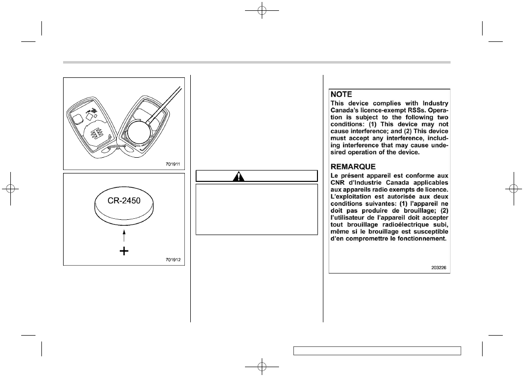
3. Remove the circuit board from the

bottom half of the case and remove
the battery and replace with new one.
Be sure to observe the (+) sign on the
old battery before removing it to ensure
that the new battery is inserted prop-

erly (battery “+” should be pointed
away from the transmitter circuit board
on battery).

4. Carefully snap the case halves back

together, reinstall the phillips screw
and test the remote engine start
system.

&

Certification for remote en-
gine starter

!

U.S.-spec. models

CAUTION

FCC WARNING

Changes or modifications not ex-
pressly approved by the party re-
sponsible for compliance could void
the user’s authority to operate the
equipment.

NOTE

This device complies with part 15 of the
FCC Rules. Operation is subject to the
following two conditions: (1) This de-
vice may not cause harmful interfer-
ence, and (2) this device must accept
any interference received, including
interference that may cause undesired
operation.

!

Canada-spec. models

Remote engine start system (dealer option)

318

(321,1)

7-7. Continuously variable
transmission

WARNING

Do not shift from the “P” or “N”
position into the “D” or “R” position
while depressing the accelerator
pedal. This may cause the vehicle
to jump forward or backward.

CAUTION

.

Observe the following precau-

tions. Otherwise, the transmis-
sion could be damaged.

– Shift into the “P” or “R” posi-

tion only after the vehicle has
completely stopped.

– Do not shift from the “D”

position into the “R” position
or vice versa until the vehicle
has completely stopped.

.

Do not race the engine for more

than 5 seconds in any position
except the “N” or “P” position
when the brake is applied or
when chocks are used in the
wheels. This may cause the
transmission fluid to overheat.

.

Never move the vehicle as fol-

lows. Doing so may result in an
unexpected accident or malfunc-
tion.

– Moving rearward by inertia

with the select lever set in a
forward driving position.

– Moving forward by inertia with

the select lever set in the “R”
position.

.

When parking the vehicle, first

securely apply the parking brake
and then place the select lever in
the “P” position. Avoid parking
for a long time with the select
lever in any other position as
doing so could result in a dead
battery.

&

Continuously variable trans-
mission features

The continuously variable transmission is
electronically controlled and provides an
infinite number of forward speeds and 1
reverse speed. It also has a manual mode
or an “L” position.

NOTE

.

When the engine coolant tempera-
ture is still low, the transmission will
shift at higher engine speeds than
when the coolant temperature is
sufficiently high in order to shorten
the warm-up time and improve dri-
veability. The gearshift timing will
automatically shift to the normal
timing after the engine has warmed
up.

.

Immediately after transmission fluid
is replaced, you may feel that the
transmission operation is somewhat
unusual. This results from invalida-
tion of data which the on-board
computer has collected and stored
in memory to allow the transmission
to shift at the most appropriate times
for the current condition of your
vehicle. Optimized shifting will be
restored as the vehicle continues to
be driven for a while.

.

When driving a CVT model under

– CONTINUED –

Continuously variable transmission

319

7

Starting

and

operating

(322,1)

continuous heavy load conditions
such as when towing a camper or
climbing a long, steep hill, the en-
gine speed or the vehicle speed may
automatically be reduced. This is not
a malfunction. This results from the
engine control function maintaining
the cooling performance of the ve-
hicle. The engine and vehicle speed
will return to a normal speed when
the engine is able to maintain the
optimum cooling performance after
the heavy load decreases. Driving
under a heavy load must be per-
formed with extreme care. Do not try
to pass a vehicle in front when
driving on an uphill slope while
towing.

.

The continuously variable transmis-
sion is a chain type system that
provides superior transmission effi-
ciency for maximum fuel economy.
At times, depending on varying
driving conditions, a chain operat-
ing sound may be heard that is
characteristic of this type of system.

&

Select lever

Type A

1

Select lever button

Type B

1

Select lever button

1

Models with “L” position

2

Models with manual mode

: With the brake pedal depressed, shift

while pressing the select lever button
in.

: Shift while pressing the select lever

button in.

: Shift without pressing the select lever

button.

The select lever has four positions, “P”,
“R”, “N”, “D” and it also has an “L” or “M”
gate.

NOTE

For some models, to protect the engine
while the select lever is in the “P” or “N”
position, the engine is controlled so
that the engine speed may not become
too high even if the accelerator pedal is

Continuously variable transmission

320

(323,1)

depressed hard.

!

P (Park)

This position is for parking the vehicle and
starting the engine. In this position, the
transmission is mechanically locked to
prevent the vehicle from rolling freely.

When you park the vehicle, first apply the
parking brake firmly, then shift into the “P”
position. Do not hold the vehicle with only
the mechanical friction of the transmission.

To shift the select lever from the “P”
position to any other position, you should
depress the brake pedal fully then move
the select lever. This prevents the vehicle
from lurching when it is started.

!

R (Reverse)

This position is for backing the vehicle. To
shift from the “N” to “R” position, stop the
vehicle completely then move the lever to
the “R” position while pressing the select
lever button in.

When the ignition switch has been turned
to the “ACC” position, the movement of the
select lever from the “N” to “R” position is
only possible by depressing the brake
pedal. For details, refer to “Shift lock
function”

P324.

!

N (Neutral)

This position is for restarting a stalled
engine. In this position, the transmission is
neutral, meaning that the wheels and
transmission are not locked. Therefore,
the vehicle will roll freely, even on the
slightest incline unless the parking brake
or foot brake is applied.

Avoid coasting with the transmission in
neutral. Engine braking has no effect in
this condition.

WARNING

Do not drive the vehicle with the
select lever in the “N” (neutral)
position. Engine braking has no
effect in this condition and the risk
of an accident is consequently in-
creased.

!

D (Drive)

This position is for normal driving. The
transmission shifts automatically and con-
tinuously into a suitable gear according to
the vehicle speed and the acceleration you
require. Also, while driving up and down a
hill, the transmission assists and controls
the driving performance and engine brak-
ing while corresponding to the road grade.

When more acceleration is required in the
“D” position, depress the accelerator pedal
fully to the floor and hold that position. The
transmission will automatically downshift.
In this case, the transmission will operate
like a conventional automatic transmis-
sion. When you release the pedal, the
transmission will return to the original gear
position.

For models with manual mode, if one of the
shift paddles behind the steering wheel is
operated while driving in the “D” position,
the transmission will temporarily switch to
the manual mode. In this mode, you can
shift into any gear position using the shift
paddles. For details about the manual
mode, refer to “Selection of manual mode”

P322. Once the vehicle speed stabi-

lizes, the transmission will switch from the
manual mode back to the “D” position for
normal driving.

– CONTINUED –

Continuously variable transmission

321

7

Starting

and

operating

(324,1)

&

Selection of manual mode (if
equipped)

Type A

Type B

With the vehicle either moving or station-
ary, move the select lever from the “D”

position to the “M” position to select the
manual mode.

Select lever/gear position indicator

1

Upshift indicator

2

Downshift indicator

3

Gear position indicator

When the manual mode is selected, the
gear position indicator and upshift indica-
tor and/or downshift indicator on the
combination meter illuminate.

The gear position indicator shows the
currently selected gear in the following
range.

.

1st-to-7th-gear range (except for
Subaru Forester Wilderness models)

.

1st-to-8th-gear range (for Subaru
Forester Wilderness models)

The upshift and downshift indicators show
when a gear shift is possible. When the
upshift indicator “

” illuminates, upshift-

ing is possible. When the downshift in-
dicator “

” illuminates, downshifting is

possible. When both indicators illuminate,
upshifting and downshifting are both pos-
sible. When the vehicle stops (for exam-
ple, at traffic signals), the downshift in-
dicator turns off.

Gearshifts can be performed using the
shift paddle behind the steering wheel.

To upshift to the next higher gear position,
pull the shift paddle that has “

+

” indicated

on it. To downshift to the next lower gear
position, pull the shift paddle that has “

indicated on it.

Continuously variable transmission

322

(325,1)

To deselect the manual mode, return the
select lever to the “D” position from the “M”
position.

CAUTION

Do not place or hang anything on the
shift paddles. Doing so may result in
accidental gear shifting.

NOTE

Please read the following points care-
fully and bear them in mind when using
the manual mode.

.

If you attempt to shift down when the
engine speed is too high, i.e., when a
downshift would push the tach-
ometer needle beyond the red zone,
beeps will be emitted to warn you
that the downshift is not possible.

.

If you attempt to shift up when the
vehicle speed is too low, the trans-
mission will not respond.

.

You can perform a skip-shift (for
example, from 4th to 2nd) by operat-
ing the shift paddle twice in rapid
succession.

.

The transmission automatically se-
lects 1st gear when the vehicle stops
moving.

.

If the temperature of the transmis-
sion fluid becomes too high, the “AT

OIL TEMP” warning light on the
combination meter will illuminate.
Immediately stop the vehicle in a
safe location and let the engine idle
until the warning light turns off.

&

Selection of “L” (if equipped)

Type A

Type B

“L” is for using engine braking when going
down a hill, etc. To select this mode, move
the select lever from the “D” position to the
“L” position.

When selected, the indicator “L” will

– CONTINUED –

Continuously variable transmission

323

7

Starting

and

operating

(326,1)

illuminate on the combination meter.

To deselect “L”, move the select lever to
the “D” position.

&

Shift lock function

The shift lock function helps prevent the
improper operation of the select lever.

.

The select lever cannot be operated
unless the ignition switch is turned to
the “ON” position and the brake pedal is
depressed.

.

The select lever cannot be moved from
the “P” position to any other position
before the brake pedal is depressed.
Depress the brake pedal first, and then
operate the select lever.

.

Only the “P” position allows you to turn
the ignition switch from the “ACC”
position to the “LOCK”/“OFF” position
and remove the key from the ignition
switch.

.

If the ignition switch is turned to the
“ACC” position while the select lever is
in the “N” position, the select lever may
not be moved to the “P” position without
depressing the brake pedal and press-
ing the select lever button.

!

Shift lock release

If the select lever cannot be operated, turn
the ignition switch back to the “ON”

position then move the select lever to the
“P” position with the select lever button
pressed and the brake pedal depressed.

If the select lever does not move after
performing the above procedure, check
and confirm the following and release the
shift lock accordingly.

.

When the select lever cannot be

shifted from “P” to “N”:

Refer to “Shift lock release using the shift
lock release button”

P324.

.

When the select lever cannot be
shifted from “N” to “R”, “P”:

Place the ignition switch in the “ACC”
position, then move the select lever to the
“P” position with the brake pedal de-
pressed.

If the select lever still does not move, refer
to “Shift lock release using the shift lock
release button”

P324.

If the shift lock cannot be released without
using the shift lock release button in the
above cases, there may be a malfunction
in the shift lock system or the vehicle
control system.

Contact a SUBARU dealer for an inspec-
tion as soon as possible.

!

Shift lock release using the shift
lock release button

Perform the following procedure to release
the shift lock.
1. Apply the parking brake and stop the

engine.

2. Wrap the tip of a flat-head screwdriver

with vinyl tape or a cloth and use it to
remove the shift lock cover. The shift
lock release button is located under the
shift lock cover.

Continuously variable transmission

324

(327,1)

3. While depressing the brake pedal,

insert a screwdriver into the hole, press
the shift lock release button using a
screwdriver, and then move the select
lever.

If the select lever does not move after
performing the above procedure, the shift
lock system may be malfunctioning. Con-
tact a SUBARU dealer for an inspection as
soon as possible.

&

Driving tips

CAUTION

If the accelerator and brake pedals
are depressed at the same time,
driving torque may be restrained.
This is not a malfunction.

.

Always apply the foot or parking brake
when the vehicle is stopped in the “D” or
“R” position.

.

Make sure to apply the parking brake
when parking your vehicle. Do not hold
the vehicle with only the mechanical
friction of the transmission.

.

Do not keep the vehicle in a stationary
position on an uphill grade by using the
“D” position. Use the brake instead.

.

The engine may, on rare occasions,
knock when the vehicle rapidly accel-
erates or rapidly pulls away from a
standstill. This phenomenon does not
indicate a malfunction.

7-8. SI-DRIVE

SI-DRIVE (SUBARU Intelligent Drive)
works to maximize engine performance,
control and efficiency.
This system consists of two modes:
Intelligent (I), Sport (S), and Sport Sharp
(S#). By operating the SI-DRIVE switches,
the character of the power unit changes.

&

Intelligent (I) mode

!

For smooth, efficient performance
driving

The linear acceleration characteristic of
the Intelligent (I) mode is ideal for normal
driving usage.
The Intelligent (I) mode provides well-
balanced performance with greater fuel

– CONTINUED –

SI-DRIVE

325

7

Starting

and

operating

(328,1)

efficiency and smooth driveability without
stress. Power delivery is moderate during
acceleration for maximum fuel efficiency.
This is ideal for around-town driving and
situations that do not require full power
output. It provides better control in difficult
driving conditions, such as slippery roads
or loose surfaces, due to gentler throttle
response.

&

Sport (S) mode (if equipped)

!

For all-around performance driving

The Sport (S) mode provides the engine
power desired by those who want to make
the driving experience their own personal
adventure.

&

Sport Sharp (S#) mode (if
equipped)

!

For maximum performance driving

For sports-minded drivers, the Sport
Sharp (S#) mode offers an exhilarating
level of engine performance and control.
The throttle becomes more responsive
regardless of the engine speed. Delivering
maximum driving enjoyment, this mode is
ideal for tackling twisting roads and for
merging or overtaking other vehicles on
the freeway with confidence.

&

SI-DRIVE switches

Type A SI-DRIVE switches

Type B SI-DRIVE switches

.

To select the Intelligent (I) mode, press
the “I” switch.

SI-DRIVE

326

(329,1)

.

To select the Sport (S) mode, press the
“S” switch.

.

To select the Sport Sharp (S#) mode,
press the “S#” switch.

NOTE

.

While the engine is cool, you cannot
change to Sport Sharp (S#) mode.

.

The next time you turn on the engine,
after you turned off the engine in the
Sport (S) mode (type A) or Sport
Sharp (S#) mode (type B), the
SI-DRIVE mode changes to the In-
telligent (I) mode.

.

If the CHECK ENGINE warning light/
malfunction indicator light illumi-
nates while the engine is running,
type A changes to the Sport (S)
mode, and type B remains in the
state that was in effect before the
warning light turned on. In this case,
it is not possible to change to
another mode.

.

If any of the SI-DRIVE indicators
blink, the SI-DRIVE system may be
m a l f u n c t i o n i n g . C o n t a c t y o u r
SUBARU dealer.

7-9. Power steering

&

Power steering warning light

&

Power steering system fea-
tures

The vehicle is equipped with an electric
power steering system. When the ignition
switch is turned to the “ON” position, the
power steering warning light on the com-
bination meter illuminates to inform the
driver that the warning system is function-
ing properly. Then, if the engine started,
the warning light turns off to inform the
driver that the steering power assist is
operational.

CAUTION

When the power steering warning
light is illuminated, there may be
more resistance when the steering
wheel is operated. Drive carefully to
the nearest SUBARU dealer and
have the vehicle inspected immedi-
ately.

NOTE

If the steering wheel is operated in the
following ways, the power steering
control system may temporarily limit
the power assist in order to prevent the
system components, such as the con-
trol computer and drive motor, from
overheating.

.

The steering wheel is operated fre-
quently and turned sharply while the
vehicle is maneuvered at extremely
low speeds, such as while frequently
turning the steering wheel during
parallel parking.

.

The steering wheel remains in the
fully turned position for a long
period of time.

At this time, there will be more resis-
tance when steering. However, this is
not a malfunction. Normal steering
force will be restored after the steering

– CONTINUED –

Power steering

327

7

Starting

and

operating

(330,1)

wheel is not operated for a while and
the power steering control system has
an opportunity to cool down. However,
if the power steering is operated in a
non-standard way which causes power
assist limitation to occur too frequently,
this may result in a malfunction of the
power steering control system.

7-10. Braking

&

Braking tips

WARNING

Never rest your foot on the brake
pedal while driving. This can cause
dangerous overheating of the
brakes and needless wear on the
brake pads.

!

When the brakes get wet

When driving in rain or after washing the
vehicle, the brakes may get wet. As a
result, brake stopping distance will be
longer. To dry the brakes, drive the vehicle
at a safe speed while lightly depressing the
brake pedal to heat up the brakes.

!

Use of engine braking

Remember to make use of engine braking
in addition to foot braking. When descend-
ing a grade, if only the foot brake is used,
the brakes may start working improperly
because of brake fluid overheating,
caused by overheated brake pads. To help
prevent this, shift to a lower gear to get
stronger engine braking.

!

Braking when a tire is punctured

Do not depress the brake pedal suddenly
when a tire is punctured. This could cause

a loss of control of the vehicle. Keep
driving straight ahead while gradually
reducing speed. Then slowly pull off the
road to a safe place.

&

Brake system

!

Two separate circuits

Your vehicle has two separate circuit brake
systems. Each circuit works diagonally
across the vehicle. If one circuit of the
brake system should fail, the other half of
the system still works. If one circuit fails,
the brake pedal will go down much closer
to the floor than usual and you will need to
press it down much harder. A much longer
distance will be needed to stop the vehicle.

!

Electronic brake booster

The vehicle is equipped with an electronic
brake booster to provide additional braking
force. Do not turn off the ignition switch
while driving because that will turn off the
brake booster, resulting in poor braking
power.
The brakes will continue to work even
when the brake booster completely stops
functioning. If this happens, you will have
to depress the pedal much harder than
during normal braking, and the braking
distance will increase.

Braking

328

(331,1)

NOTE

When the following operations are
performed, an operating sound from
the electronic brake boost control
module may be heard. This is not a
malfunction.

.

The brake pedal was operated.

.

The driver’s door was opened.

.

The EyeSight function was acti-
vated.

.

Several minutes have passed after
the engine stopped.

!

Supplemental booster function
when electronic brake booster
fails

If there is a malfunction in the braking
system, the power for the braking will be
stored by controlling the hydraulic pres-
sure of the VDC system.
When the brake pedal is depressed while
the supplemental booster function is oper-
ating, an operation sound and brake pedal
vibration may be generated.

!

Brake assist system

WARNING

Do not be overconfident about the
brake assist. It is not a system that
brings more braking ability to the
vehicle beyond its braking capabil-

ity. Always use the utmost care
when driving regarding vehicle
speed and safe distance.

CAUTION

When you need to brake suddenly,
continue depressing the brake pedal
strongly to bring the effect of the
brake assist.

Brake assist is a driver assistance system.
It assists the brake power when the driver
cannot depress the brake pedal strongly
and the brake power is insufficient.
Brake assist generates the brake power
according to the speed at which the driver
depresses the brake pedal.

NOTE

When you depress the brake pedal
strongly or suddenly, the following will
occur. However, even though these
occur, they do not indicate any mal-
functions, and the brake assist system
is operating properly.

.

You might feel that the brake pedal is
applied by lighter force and gener-
ates a greater braking force.

.

You might hear an ABS operating
noise from the engine compartment.

&

Disc brake pad wear warning
indicators

The disc brake pad wear warning indica-
tors on the disc brakes give a warning
noise when the brake pads are worn.
If a squeaking or scraping noise is heard
from the disc brakes while braking, im-
mediately have your vehicle checked by
your SUBARU dealer.

Braking

329

7

Starting

and

operating

(332,1)

7-11. ABS (Anti-lock Brake
System)

The ABS prevents the lock-up of wheels
which may occur during sudden braking or
braking on slippery road surfaces. This
helps prevent the loss of steering control
and directional stability caused by wheel
lock-up.

When the ABS is operating, you may hear
a chattering noise or feel a slight vibration
in the brake pedal. This is normal when the
ABS operates.

The ABS will not operate when the vehicle
speed is below approximately 6 mph (10
km/h).

WARNING

Always use the utmost care in driv-
ing – overconfidence because you
are driving a vehicle with the ABS
could easily lead to a serious acci-
dent.

CAUTION

.

The ABS does not always de-

crease stopping distance. You
should always maintain a safe
following distance from other
vehicles.

.

When driving on badly surfaced

roads, gravel roads, icy roads, or
over newly fallen snow, stopping
distances may be longer for a
vehicle with the ABS than one
without. Therefore, when driving
under these conditions, reduce
your speed and leave ample dis-
tance from other vehicles.

.

When tire chains are installed,

stopping distances may be long-
er for a vehicle with the ABS than
one without. Be sure to reduce
your speed and maintain a safe
distance from the vehicle in front.

.

When you feel the ABS operating,

you should maintain constant
brake pedal pressure. Do not
pump the brake pedal since
doing so may defeat the opera-
tion of the ABS.

&

ABS self-check

Just after the vehicle is started, you may
feel on the brake pedal a vibration similar
to when the ABS operates, and you may
also hear the sound of the ABS working
from the engine compartment. This is
caused by an automatic functional test of
the ABS being carried out and does not
indicate a malfunction.

&

ABS warning light

Refer to “ABS warning light”

P175.

ABS (Anti-lock Brake System)

330

(333,1)

7-12. Electronic Brake Force
Distribution (EBD) system

The EBD system maximizes the effective-
ness of the brakes by allowing the rear
brakes to supply a greater proportion of the
braking force. It functions by adjusting the
distribution of braking force to the rear
wheels in accordance with the vehicle’s
loading condition and speed.
The EBD system is an integral part of the
ABS and uses some of the ABS compo-
nents to perform its function of optimizing
the distribution of braking force. If any of
the ABS components used by the EBD
system malfunction, the EBD system also
stops working.

When the EBD system is operating, you
may hear a chattering noise or feel a slight
vibration in the brake pedal. This is normal
and does not indicate a malfunction.

&

If EBD system malfunctions

If a malfunction occurs in the EBD system,
the system stops working and the following
warning lights illuminate simultaneously.

.

Brake system warning light

.

ABS warning light

.

Vehicle Dynamics Control warning light

If the both warning light remains on even
though the parking brake is released, the
brake fluid level may be low or there could
be a problem with the EBD system. Park
the vehicle in a safe place immediately and
contact a Subaru dealer.

WARNING

.

Driving with the brake system

warning light illuminated is dan-
gerous. This indicates your brake
system may not be working prop-
erly. If the light remains illumi-
nated, have the brakes inspected
by a SUBARU dealer immedi-
ately.

.

If at all in doubt about whether the

brakes are operating properly, do
not drive the vehicle. Have your
vehicle towed to the nearest
SUBARU dealer for repair.

Electronic Brake Force Distribution (EBD) system

331

7

Starting

and

operating

(334,1)

7-13. Vehicle Dynamics Con-
trol system

&

Safety precautions

WARNING

Always use the utmost care in driv-
ing – overconfidence because you
are driving a vehicle with the Vehicle
Dynamics Control system could ea-
sily lead to a serious accident.

CAUTION

.

Even if your vehicle is equipped

with the Vehicle Dynamics Con-
trol system, winter tires should
be used when driving on snow-
covered or icy roads; in addition,
vehicle speed should be reduced
considerably. Simply having a
Vehicle Dynamics Control sys-
tem does not guarantee that the
vehicle will be able to avoid
accidents in any situation.

.

Activation of the Vehicle Dy-

namics Control system is an
indication that the road on which
the vehicle is traveling has a
slippery surface; since having

Vehicle Dynamics Control is no
guarantee that full vehicle control
will be maintained at all times and
under all conditions, its activa-
tion should be seen as a sign that
the speed of the vehicle should
be reduced considerably.

.

Whenever suspension compo-

nents, steering components, or
an axle are removed from a
vehicle, have an inspection of
that system performed by an
authorized SUBARU dealer.

.

The following precautions should

be observed in order to ensure
that the Vehicle Dynamics Con-
trol system is operating properly:

– All four wheels should be

fitted with tires of the same
size, type, and brand. Further-
more, the amount of wear
should be the same for all four
tires.

– Keep the tire pressure at the

proper level as shown on the
vehicle placard attached to
the driver’s side door pillar.

– Use only the specified tempor-

ary spare tire to replace a flat
tire. With a temporary spare
tire, the effectiveness of the

Vehicle Dynamics Control
system is reduced and this
should be taken into account
when driving the vehicle in
such a condition.

.

If non-matching tires are used,

the Vehicle Dynamics Control
system may not operate cor-
rectly.

.

The Vehicle Dynamics Control

system helps prevent unstable
vehicle motion such as skidding
using control of the brakes and
engine power. Do not turn off the
Vehicle Dynamics Control sys-
tem unless it is absolutely neces-
sary. If you must turn off the
Vehicle Dynamics Control sys-
tem, drive very carefully accord-
ing to the road surface condi-
tions.

&

System features

In the event of wheelspin and/or skidding
on a slippery road surface and/or during
cornering and/or an evasive maneuver,
the Vehicle Dynamics Control system
adjusts the engine’s output and the
wheels’ respective braking forces to help
maintain traction and directional control.

Vehicle Dynamics Control system

332

(335,1)

.

Traction Control Function

The traction control function is designed to
prevent spinning of the driving wheels on
slippery road surfaces, thereby helping to
maintain traction and directional control.
Activation of this function is shown by
flashing the Vehicle Dynamics Control
operation indicator light.

.

Skid Suppression Function

The skid suppression function is designed
to help maintain directional stability by
suppressing the wheels’ tendency to slide
sideways during steering operations. Acti-
vation of this function is shown by flashing
the Vehicle Dynamics Control operation
indicator light.

NOTE

.

The Vehicle Dynamics Control sys-
tem may be considered normal when
the following conditions occur.

– Slight twitching of the brake

pedal is felt.

– The vehicle or steering wheel

shakes to a small degree.

– An operating sound from the

engine compartment is heard
briefly when starting the engine
and when driving off after start-
ing the engine.

– The brake pedal seems to jolt

when driving off after starting the
engine.

.

In the circumstances shown in the
following list, the vehicle may be
less stable than it feels to the driver.
The Vehicle Dynamics Control sys-
tem may therefore operate. Such
operation does not indicate a sys-
tem malfunction.

– On gravel-covered or rutted

roads

– On unfinished roads
– When the vehicle is towing a

trailer

– When the vehicle is fitted with

snow tires or winter tires.

.

Activation of the Vehicle Dynamics
Control system will cause operation
of the steering wheel to feel slightly
different compared to that for nor-
mal conditions.

.

It is always important to reduce
speed when approaching a corner,
even if your vehicle is equipped with
the Vehicle Dynamics Control sys-
tem.

.

Always turn off the engine before
replacing a tire. Failure to do so may
render the Vehicle Dynamics Control
system unable to operate correctly.

&

Vehicle Dynamics Control
system monitor

Refer to “Vehicle Dynamics Control warn-
ing light/Vehicle Dynamics Control opera-
tion indicator light”

P179 and “Vehicle

Dynamics Control OFF indicator light”

P180.

&

Vehicle Dynamics Control
OFF switch

Type A

– CONTINUED –

Vehicle Dynamics Control system

333

7

Starting

and

operating


Content      ..     18      19      20      21     ..