Subaru Forester (2023 year). Manual in english - page 18
 

  Index      Manuals     Subaru Forester (2023 year). Manual in english


Search            copyright infringement  


Content      ..     16      17      18      19     ..


Subaru Forester (2023 year). Manual in english - page 18


(287,1)

.

Do not use more than one floor

mat.

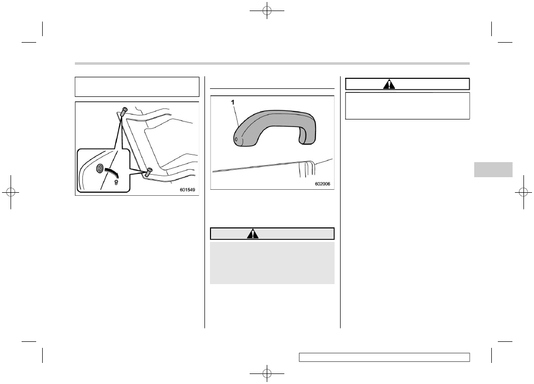
Retaining pins are located on the driver’s
side floor.
The floor mat should be properly secured
using the built-in grommets, by placing the
grommets over the pins and pushing them
downward.

6-9. Assist grip

1

Assist grip

The assist grip is to be held to support the
body of the passengers when they are in
the seat and the vehicle is moving.

WARNING

Do not hold the assist grip when
getting up from the seat. Holding
and pulling the assist grip in the
wrong way could break the grip and
possibly cause injury.

CAUTION

Do not attach heavy objects to the
assist grip. Doing so could break it
and damage the object.

Assist grip

285

6

Interior

equipment

(288,1)

6-10. Shopping bag hook

CAUTION

Do not hang items on the shopping
bag hook that weigh 6 lbs (3 kg) or
more.

A shopping bag hook is attached to each
side of the cargo area.

6-11. Convenience hook

CAUTION

.

Do not hang items on the conve-

nience hook that weigh 6 lbs (3
kg) or more. Depending on the
conditions of use (for example, in
low temperatures, etc.), the rear
gate may lower even with lighter
loads. However, this is not a
malfunction. Be careful not to hit
your head or other body parts.

.

When using the convenience

hook, do not try to close the rear
gate. Doing so may cause the
item on the hook to be jammed in
the rear gate and damaged. Re-
move the item from the hook
before closing the rear gate.

A convenience hook is attached to the rear
gate trim. When the rear gate is open, you
can hang a lantern, wet suit, etc. on the
hook.

Shopping bag hook

286

(289,1)

6-12. Cargo area cover (if
equipped)

The cargo area cover is provided for
covering the cargo area and to protect its
contents from direct sunlight. This cover is
detachable to make room for additional
cargo.

&

Using the cover

To extend the cover, pull the end of the
cover out of the housing, then insert its
hooks into the catches as shown. To
rewind it, unhook it from the catches and
it will rewind automatically. You should
hold on to the cover and guide it back into
the cover housing while it is rewinding.

WARNING

Do not place anything on the ex-
tended cover. Putting excessive
weight on the extended cover can
break it and an object on the cover
could tumble forward in the event of
a sudden stop or collision. This
could cause serious injury.

CAUTION

Be careful not to scratch the rear
gate stays while extending and re-
winding the cover. Scratches on the
stays could cause leakage of gas
from the stays, which may result in
their inability to hold the rear gate
open.

&

To install the front part of the
cover

CAUTION

For models with a reclining rear
seatback, when reclining, move the
front part of the cover back so that it
is not damaged.

1. Align the right side of the front cover

with the triangle mark before fixing the
cover in place.

2. Align the left side of the front cover with

the triangle mark before fixing the
cover in place.

3. Push the front cover to the right side

and adjust the size of the bar as
necessary.

– CONTINUED –

Cargo area cover

287

6

Interior

equipment

(290,1)

&

To remove the front cover

1. Push the front cover to the right side

and shorten the bar.

2. Remove the front cover.

&

To remove the cover housing

1. Rewind the cover.

2. Push the cover housing to the right

side and shorten it.

3. Take it off the retainer.

&

Stowage of the cargo area
cover

The cargo area cover can be stowed in
under the cargo floor.

1. Pull the strap to open the center part of

the cargo floor lid, and then remove the
lid.

2. Remove the left and right parts of the

cargo floor lid.

3. Stow the cover housing in the cargo

area end.

Cargo area cover

288

(291,1)

&

To install the cover housing

1. Insert the protrusion located on the

right end of the sleeve into the recess
of the retainer.

2. Push the cover housing to the right

side and shorten the bar.

3. Insert the other protrusion into the

recess of the other retainer.

6-13. Cargo tie-down hooks

The cargo area is equipped with several
tie-down hooks so that cargo can be
secured with a cargo net or ropes.
When using the tie-down hooks, turn them
down out of the storing recesses.

CAUTION

The cargo tie-down hooks are de-
signed only for securing light cargo.
Never try to secure cargo that ex-
ceeds the capacity of the hooks. The
maximum load capacity is 22 lbs (10
kg) per hook.

Cargo tie-down hooks

289

6

Interior

equipment

(292,1)

6-14. Cargo upper hooks

There are two hooks on the lining in the
cargo area. Use them to hang or secure
lightweight objects when the vehicle is
stopped.

WARNING

Do not hang anything on the hooks
that produces a flame. Flammable
gas may fill the inside of the vehicle
or cause a fire.

CAUTION

When using a hook, observe the
following precautions.

.

Do not drive with an object hang-

ing on a hook. There is a risk that
you will not be able to see behind
you, or that an object may be
propelled when braking or start-
ing suddenly, which could lead to
an accident or injury.

.

Do not hang heavy or large ob-

jects on the hook.

Maximum load capacity: 6 lbs (3
kg)

.

Do not use the hooks to secure

the child restraint system.

.

On hot, sunny days, do not leave

objects hanging from the hooks
for a long time. If the inside of the
car becomes hot, the hook may
be deformed, and the hanging
objects may fall.

6-15. Under-floor storage
compartment (if equipped)

NOTE

The shape of the storage compartment
may be different depending on the
model.

The storage compartment is located under
the floor of the cargo area and can be used
to store small items. Pull the strap to open
the center part of the cargo floor lid, and
then remove the lid.

Cargo upper hooks

290

(293,1)

CAUTION

.

Always keep the lid of the storage

compartment closed while driv-
ing to reduce the risk of injury in
the event of sudden stop or an
accident.

.

Do not store spray cans, contain-

ers with flammable or corrosive
liquids or any other dangerous
items in the storage compart-
ment.

6-16. Front View Monitor (if
equipped)

The image from the camera mounted
inside the front grille is displayed in the
multi-function display (color LCD). This
eliminates blind spots and allows the driver
to check the forward direction of both
sides.

WARNING

.

Never rely on only the Front View

Monitor when driving the vehicle.
The image on the monitor screen
may be different from the actual
situation. If you drive the vehicle
by viewing only the monitor im-
age, a collision or an unexpected

accident may occur. When driv-
ing the vehicle, always check the
traffic around the vehicle directly
with your eyes and the mirrors.

.

Always operate the vehicle as

you would without the Front View
Monitor.

.

Do not use the Front View Monitor

in the following situations.

– You are driving on a dirt road

or a road covered in snow.

– The camera malfunctions (e.g.

the lens or bracket is broken).

.

If the outside temperature is low,

the monitor screen may become
dark or the image may become
dim. In particular, the image of a
moving object may be distorted
or disappear from the screen.
You must always check the traffic
around the vehicle directly with
your eyes when driving it.

– CONTINUED –

Front View Monitor

291

6

Interior

equipment

(294,1)

&

How to access the Front View
Monitor

1

Front view monitor switch

To change over to the camera screen,
perform either of the following operations
when the ignition switch is in the “ACC” or
“ON” position.

.

Press the front view monitor switch.

.

Shift the select lever from “R” to “D”.

&

How to cancel the Front View
Monitor

!

Manual cancellation

.

Press the front view monitor switch.

.

Press the INFO button.

!

Automatic cancellation

If any of the following conditions are met,
the Front View Monitor is canceled auto-
matically.

After accessing the Front View Monitor
by pressing the front view monitor
switch:

.

Approximately 3 minutes have passed
since the last operation.

.

The vehicle speed becomes 13 mph
(20 km/h) or more*.

.

The select lever is shifted to the “P”
position.

.

The parking brake is applied.

*: The Front View Monitor can be activated

when pressing the front view monitor switch,
regardless of the vehicle speed.

*: When the Front View Monitor is activated at

speeds of more than 13 mph (20 km/h), to
cancel the Front View Monitor, the vehicle
speed needs to be decreased to less than 13
mph (20 km/h) and then increased to more
than 13 mph (20 km/h).

After accessing the Front View Monitor
using the select lever:

.

Shift the select lever into the “P”
position.

.

The vehicle speed becomes 5 mph (8
km/h) or more.

.

Approximately 9 seconds have passed
since the last operation.

.

The parking brake is applied.

&

How to adjust the display
contrast and brightness

The contrast and brightness of the front
view monitor display can be adjusted. For
details, refer to “Camera settings”

P222.

Front View Monitor

292

(295,1)

&

Range of image on screen

A

Traffic intersection with a poor visibility
view

B

Parking facing a wall

1

Range of displayed image

2

Obstacles (e.g., buildings, fences or
other vehicles)

WARNING

Because the range of the image
captured by the camera is limited,
always check the traffic around the
vehicle directly with your eyes when
driving the vehicle.

NOTE

.

The range of the displayed image
may differ depending on the vehicle
status or the road surface status.

.

Because the Front View Monitor
system uses a specially designed
lens, the sense of distance in the
displayed image is different from the
actual distance.

.

The camera image may be difficult to
view in the following situations. This
is not a malfunction.

– Dark place (at night)
– High or low temperature around

the lens

– Water contacts lens or in high

humidity (rainy weather)

– There are foreign materials (such

as mud) around the camera.

– Sunlight or headlight beam di-

rectly shines towards the camera
lens.

.

Under an artificial light such as a
fluorescent lamp, sodium-vapor
lamp or mercury lamp, the lighted
portion may look like it is flickering
(flicker phenomenon).

.

While the display has cooled down,
the image may leave traces or be-
come darker than usual, causing a
difficulty in viewing the screen. Al-
ways check the traffic around the
vehicle directly with your eyes while
driving the vehicle.

.

The following incidents should not
be deemed a malfunction.

– The camera lens may become

foggy when the humidity is high
on a rainy day.

– The light from a vehicle or build-

ing located ahead may be re-
flected towards the camera im-
age while driving at night.

– In a dark place or while driving at

night, the camera image may be
adjusted to make noises less
visible. Therefore, the image
may look like a monochromatic
image or the image colors may
differ from the actual colors. The
camera image may be deterio-
rated in regard to sharpness at
the center and four corners of the
screen. This is not a malfunction.

– CONTINUED –

Front View Monitor

293

6

Interior

equipment

(296,1)

&

Guiding line

1

Guiding line

2

Warning message

The guiding line that indicates the width
and the front end of your vehicle is
displayed on the display.

&

Handling of camera

CAUTION

Observe the following instructions.
Otherwise, the system may malfunc-
tion.

.

Do not apply any strong impact to

the camera such as banging it or
hitting it with an object. The
mounting angle may change.

.

The camera unit is a waterproof

structure. Do not attempt to re-
move, disassemble or modify the
unit.

.

Do not rub strongly or polish the

camera lens with a hard brush or
abrasive compounds. The lens
may be scratched resulting in an
adverse effect to the camera
image.

.

The camera lens is made of glass

or plastic. Do not allow any
organic solvent, body wax, oil
film remover or glass coating
agent to become attached on the
lens surface. If any becomes
attached, remove it immediately.

.

Do not expose the camera lens to

any sudden temperature change,
for example, spraying hot water
on it in cold weather.

.

Do not apply the water jet of a

high pressure washer to the cam-
era or the surrounding area when
cleaning the vehicle. The impact
by the strong water pressure may
cause the camera to come off.
Also, water may enter inside the
camera and cause a malfunction.

.

If the camera is exposed to any

impact, it may lead to malfunction

of the camera. Have the camera
inspected by your SUBARU deal-
er as soon as possible.

.

Do not use a steam cleaner under

any circumstances. Some types
of steam cleaners inject hot
steam.

.

The camera surface may be da-

maged by a flying stone.

NOTE

If the camera lens is contaminated, no
sharp image is available. When the
camera is contaminated with water
drops, snow or mud, wash it with water
and wipe away any moisture with a soft
cloth. If it heavily gets dirty, wash it with
a neutral detergent.

Front View Monitor

294

(297,1)

6-17. Rear View Camera

Refer to the separate navigation/audio
Owner’s Manual.

Rear View Camera

295

6

Interior

equipment

(299,1)

7-1. Fuel .................................................................. 299

Fuel requirements............................................... 299
Fuel filler lid and cap .......................................... 300

7-2. State emission testing (U.S. only) ................. 303
7-3. Preparing to drive........................................... 305
7-4. Starting and stopping the engine (models

without push-button start system) .............. 305

Starting engine ................................................... 306
Stopping the engine ........................................... 307
Steering lock ...................................................... 307

7-5. Starting and stopping engine (models with

push-button start system)............................ 308

Safety precautions.............................................. 308
Operating range for push-button start system ..... 308
Starting engine ................................................... 308
Stopping engine ................................................. 309
When access key fob does not operate

properly............................................................ 310

Steering lock ...................................................... 310

7-6. Remote engine start system

(dealer option) ............................................... 311

Remote engine starter transceiver (fob) .............. 311
Alternate operation method for models with

“keyless access with push-button start
system”............................................................ 315

Entering the vehicle while it is running via

remote start (models without “keyless access
with push-button start system”) ........................ 315

Entering the vehicle while it is running via

remote start (models with “keyless access
with push-button start system”) ........................ 316

Entering the vehicle following remote engine

start shutdown ................................................. 316

Pre-heating or pre-cooling the interior of

the vehicle ....................................................... 316

Remote transmitter program (Remote engine

starter transceiver) ........................................... 316

System maintenance .......................................... 317
Certification for remote engine starter ................ 318

7-7. Continuously variable transmission ..............319

Continuously variable transmission features ...... 319
Select lever ........................................................ 320
Selection of manual mode (if equipped).............. 322
Selection of “L” (if equipped) ............................. 323
Shift lock function.............................................. 324
Driving tips ........................................................ 325

7-8. SI-DRIVE...........................................................325

Intelligent (I) mode ............................................. 325
Sport (S) mode (if equipped) .............................. 326
Sport Sharp (S#) mode (if equipped)................... 326
SI-DRIVE switches.............................................. 326

7-9. Power steering.................................................327

Power steering warning light .............................. 327
Power steering system features ......................... 327

7-10. Braking ...........................................................328

Braking tips ....................................................... 328
Brake system ..................................................... 328
Disc brake pad wear warning indicators ............. 329

7-11. ABS (Anti-lock Brake System)......................330

ABS self-check .................................................. 330
ABS warning light .............................................. 330

Starting and operating

7

Starting

and

operating

(300,1)

7-12. Electronic Brake Force Distribution

(EBD) system ................................................ 331

If EBD system malfunctions ................................ 331

7-13. Vehicle Dynamics Control system .............. 332

Safety precautions.............................................. 332
System features.................................................. 332
Vehicle Dynamics Control system monitor .......... 333
Vehicle Dynamics Control OFF switch................. 333

7-14. X-MODE (if equipped)................................... 335

To activate/deactivate X-MODE............................ 336
Hill descent control function ............................... 338

7-15. Tire pressure monitoring system (TPMS)

(U.S.-spec. models)....................................... 339

7-16. Parking your vehicle..................................... 341

Electronic parking brake ..................................... 341
Parking tips ........................................................ 347

7-17. Auto Start Stop system ................................ 348

System operation ............................................... 348
Displaying the Auto Start Stop system status ..... 352
System warning.................................................. 352

7-18. Hill start assist system................................. 352
7-19. BSD/RCTA (if equipped) ............................... 354

System features.................................................. 354
System operation ............................................... 357
BSD/RCTA approach indicator light/warning

buzzer .............................................................. 358

BSD/RCTA OFF indicator light............................. 360

BSD/RCTA warning light..................................... 361
BSD/RCTA OFF switch ....................................... 361
Certification for the BSD/RCTA ........................... 362
Handling of radar sensors .................................. 363

7-20. Reverse Automatic Braking (RAB)

system (if equipped) .....................................363

Reverse Automatic Braking (RAB) system

overview .......................................................... 364

Operating conditions.......................................... 366
Reverse Automatic Braking (RAB) system

operation ......................................................... 369

Canceling the Reverse Automatic Braking

(RAB) system operation ................................... 372

Reverse Automatic Braking (RAB) system

ON/OFF setting ................................................ 372

RAB warning indicator ....................................... 373
Handling of the sonar sensors ........................... 373

7-21. Driver Monitoring System (if equipped) ......374

User recognition function ................................... 378
Inattentive/drowsy driving warning ..................... 380
Driver Monitoring System indicator/warning ....... 382
Using the Driver Monitoring System ................... 382
Registering and deleting a user .......................... 384
Registering and deleting driver position

personalization ................................................ 384

Driver Monitoring System ON/OFF settings......... 385
Gesture control .................................................. 386
How to get the source code using the open

source ............................................................. 388

Starting and operating

(301,1)

7-1. Fuel

CAUTION

.

Use of a fuel which is low in

quality or use of an inappropriate
fuel additive may cause damage
to the engine and/or fuel system.

.

Some gas stations, particularly

those in high altitude areas, offer
fuels posted as regular octane
gasoline with an octane rating
below 87 AKI (90 RON). Use of
those fuels is not recommended.

&

Fuel requirements

The engine is designed to operate using

unleaded gasoline

with an octane rating

of

87 AKI (90 RON) or higher

.

!

Fuel octane rating

Using a gasoline with a lower octane rating
can cause persistent and heavy knocking,
which can damage the engine. Do not be
concerned if your vehicle sometimes
knocks lightly when you drive up a hill or
when you accelerate. Contact your
SUBARU dealer if you use a fuel with the
specified octane rating and your vehicle
knocks heavily or persistently.

!

RON

This octane rating is the Research Octane
Number.

!

AKI

This octane rating is the average of the
Research Octane and Motor Octane num-
bers and is commonly referred to as the
Anti Knock Index (AKI).

!

Unleaded gasoline

The neck of the fuel filler pipe is designed
to accept only an unleaded gasoline filler
nozzle. Under no circumstances should
leaded gasoline be used because it will
damage the emission control system and
may impair driveability and fuel economy.

!

Reformulated gasoline

SUBARU supports the use of reformulated
gasoline when available. Reformulated
gasoline has been blended to burn more
cleanly and reduce vehicle emissions.

!

MMT

Some gasoline contains an octane-enhan-
cing additive called MMT (Methylcyclo-
pentadienyl Manganese Tricarbonyl). If
you use such fuels, your emission control
system performance may deteriorate and
the CHECK ENGINE warning light/Mal-
function indicator light may turn on. If this
happens, return to your authorized

SUBARU dealer for service. If it is deter-
mined that the condition is caused by the
type of fuel used, repairs may not be
covered by your warranty.

!

Gasoline for cleaner air

Your use of gasoline with detergent ad-
ditives will help prevent deposits from
forming in your engine and fuel system.
This helps keep your engine in tune and
your emission control system working
properly, and is a way of doing your part
for cleaner air. If you continuously use a
high-quality fuel with the proper detergent
and other additives, you should never
need to add any fuel system cleaning
agents to your fuel tank.

Many gasolines are now blended with
materials called oxygenates. Use of these
fuels can also help keep the air cleaner.
Oxygenated blend fuels, such as ethanol
(ethyl or grain alcohol) may be used in your
vehicle, but should contain no more than
10% ethanol for the proper operation of
your SUBARU.

Do not use any gasoline that contains
more than 10% ethanol, including from any
pump labeled, E15, E30, E50 or E85
(which are only some examples of fuel
containing more than 10% ethanol).

In addition, some gasoline suppliers are

– CONTINUED –

Fuel

299

7

Starting

and

operating

(302,1)

now producing reformulated gasolines,
which are designed to reduce vehicle
emissions. SUBARU approves the use of
reformulated gasoline.

If you are not sure what the fuel contains,
you should ask your service station op-
erators if their gasolines contain deter-
gents and oxygenates and if they have
been reformulated to reduce vehicle emis-
sions.

As additional guidance, only use fuels
suited for your vehicle as explained in the
following description.

.

Fuel should be unleaded and have an
octane rating no lower than that speci-
fied in this manual.

.

Methanol (methyl or wood alcohol) is
sometimes mixed with unleaded gaso-
line. Methanol can be used in your
vehicle

ONLY

if it does not exceed 5%

of the fuel mixture

AND

if it is accom-

panied by sufficient quantities of the
proper cosolvents and corrosion inhibi-
tors required to prevent damage to the
fuel system. Do not use fuel containing
methanol

EXCEPT

under these condi-

tions.

.

If undesirable driveability problems are
experienced and you suspect they may
be fuel related, try a different brand of
gasoline before seeking service at your

SUBARU dealer.

.

Fuel system damage or driveability
problems which result from the use of
improper fuel are not covered under the
SUBARU Limited Warranty.

CAUTION

Do not let fuel spill on the exterior
surfaces of the vehicle. Because fuel
may damage the paint, be sure to
wipe off any spilled fuel quickly.
Paint damage caused by spilled fuel
is not covered under the SUBARU
Limited Warranty.

&

Fuel filler lid and cap

!

Locations of the fuel filler lid

!

Refueling

Only one person should be involved in
refueling. Do not allow others to approach
the area of the vehicle near the fuel filler
pipe while refueling is in progress.
Be sure to observe any other precautions
that are posted at the service station.

1. Before refueling, stop the vehicle, then

turn off the ignition switch to turn off all
the electrical components. At this time,
the fuel filler lid also unlocks.

NOTE

When you lock the door, the fuel filler
lid also locks. To unlock the fuel filler
lid, perform one of the operations
below.

– Press the unlock button on the

key fob.

– Press the unlock side of the

power door locking switch.

2. Push the rear side of the fuel filler lid.
3. The fuel filler lid opens automatically.

Open it further by hand.

WARNING

Before opening the fuel filler cap,
first touch the vehicle body or a
metal portion of the fuel pump or
similar object to discharge any sta-

Fuel

300

(303,1)

tic electricity that may be present on
your body. If your body is carrying
an electrostatic charge, there is a
possibility that an electric spark
could ignite the fuel, which could
burn you. To avoid acquiring a new
static electric charge, do not get
back into the vehicle while refueling
is in progress.

1

Open

2

Close

4. Remove the fuel filler cap by turning it

slowly counterclockwise.

WARNING

.

Gasoline vapor is highly flam-

mable. Before refueling, always
turn the ignition switch to the
“LOCK”/“OFF” position first and
then close all vehicle doors and
windows. Make sure that there
are no lighted cigarettes, open
flames or electrical sparks in the
adjacent area. Only handle fuel
outdoors. Quickly wipe up any
spilled fuel.

.

When opening the cap, grasp it

firmly and turn it slowly to the left.
Do not remove the cap quickly.
Fuel may be under pressure and
spray out of the fuel filler neck,
especially in hot weather. If you
hear a hissing sound while you
are removing the cap, wait for the
sound to stop and then slowly
open the cap to prevent fuel from
spraying out and creating a fire
hazard.

5. Set the fuel filler cap on the cap holder

inside the fuel filler lid.

WARNING

.

When refueling, insert the fuel

nozzle securely into the fuel filler
pipe. If the nozzle is lifted or not
fully inserted, its automatic stop-
ping mechanism may not func-
tion, causing fuel to overflow the
tank and creating a fire hazard.

– CONTINUED –

Fuel

301

7

Starting

and

operating


Content      ..     16      17      18      19     ..