Subaru BRZ (2023 year). Manual in english - page 13
368
Replacement of Wiper Blades
If you cannot eliminate the streaking even
When you wish to raise the
CAUTION
after following this method, replace the
passenger-side wiper arm, first
wiper blades using the following proce-
raise the driver-side wiper arm.
Hold the wiper arm when replacing
dures.
Otherwise, the passenger-side
the wiper blade. Holding the wiper
wiper assembly and driver-side
blade, may result in blade deforma-
wiper assembly will touch each
■ Windshield Wiper Blade
tion.
other, possibly resulting in
Assembly
scratches.
Return the passenger-side wiper
NOTE
arm to its original position before
Do not lower the wiper arm while the
returning the driver-side wiper
wiper blade assembly is removed.
arm to its original position. Other-
wise, the passenger-side wiper
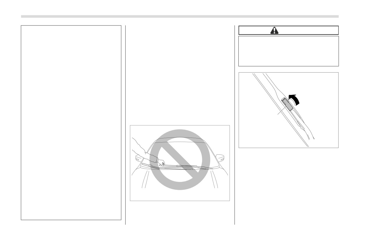
1. Raise the wiper arm off the windshield.
assembly and driver-side wiper
First raise the driver’s side wiper arm and
assembly will touch each other,
then raise the front passenger’s side wiper
1
arm.
possibly resulting in scratches.
When returning the raised wipers
to the original positions, return
the wipers slowly on the wind-
B02111
shield by hand. Returning the
wipers from the detached posi-
1)
Lock cover
tions by the spring operation
2. Hold the wiper blade connection by
might change the shape of the
wiper arm or scratch the wind-
hand, open the lock cover to release the
shield.
lock.
While removing the wiper blades
from the wiper arms, do not
return the wiper arms to the orig-
B01729
inal positions. Otherwise, the
windshield surface may be
scratched.
Replacement of Wiper Blades
369
After installing the wiper blade assembly,
close the lock cover and check that the
connection part is locked completely.
5. Hold the wiper arm by hand and slowly
lower it in position.
■ Windshield Wiper Blade
Rubber
1
1
B02112
B00504
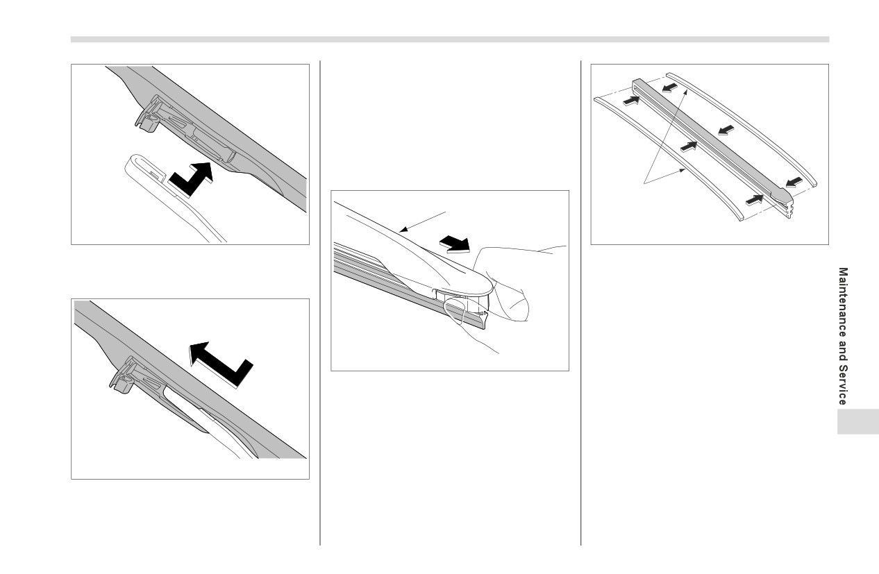
3. Remove the wiper blade assembly by
1) Metal spines
holding its pivot area and pushing it in the
2. If the new blade rubber is not provided
direction shown by the arrow.
with two metal spines, remove the metal
spines from the old blade rubber and
install them in the new blade rubber.
B02114
1) Support
1. Grasp the locked end of the blade
rubber assembly and pull it firmly until the
11
stoppers on the rubber are free of the
support.
B02113
4. When installing the wiper blade
assembly, align it with the wiper arm
connection part and then slide it in the
opposite direction of removal to install.
- CONTINUED -
370
Battery
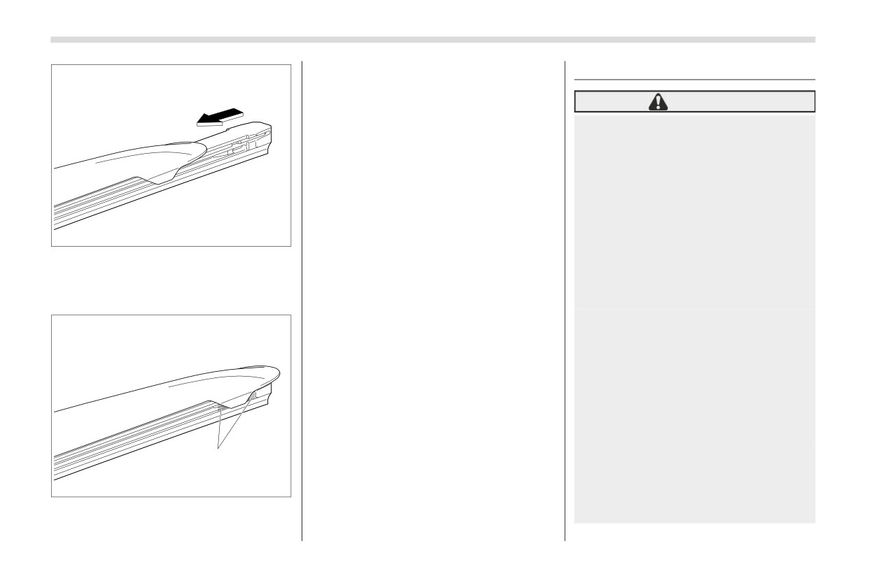
4. Be sure to position the claws at the
11-25. Battery
end of the support between the stoppers
on the rubber as shown. If the rubber is
WARNING
not retained properly, the wiper blade may
scratch the windshield.
Before beginning work on or near
any battery, be sure to extinguish
all cigarettes, matches, and
lighters. Never expose a battery
to an open flame or electric
sparks. Batteries give off a gas
which is highly flammable and
explosive.
B02115
For safety, in case an explosion
3. Align the claws of the support with the
does occur, wear eye protection
grooves in the rubber and slide the blade
or shield your eyes when working
rubber assembly into the support until it
near any battery. Never lean over
locks.
a battery.
Do not let battery fluid contact
eyes, skin, fabrics, or paint
because battery fluid is a corro-
sive acid. If battery fluid gets on
your skin or in your eyes, immedi-
ately flush the area with water
thoroughly. Seek medical help
immediately if acid has entered
the eyes.
1
If battery fluid is accidentally
swallowed, immediately drink a
B02116
large amount of milk or water,
and seek medical attention
1) Stopper
immediately.
Fuses
371
To lessen the risk of sparks,
It is unnecessary to periodically check the
11-26. Fuses
battery fluid level or periodically refill with
remove rings, metal watchbands,
distilled water.
and other metal jewelry. Never
CAUTION
allow metal tools to contact the
positive battery terminal and
Never replace a fuse with one hav-
anything connected to it WHILE
ing a higher rating or with material
you are at the same time in
other than a fuse because serious
contact with any other metallic
damage or a fire could result.
portion of the vehicle because a
short circuit will result.
NOTE
Keep everyone including children
Fuse rating and using circuit are
away from the battery.
described on the fuse box cover.
Charge the battery in a well-venti-
The fuses are designed to melt during an
lated area.
overload to prevent damage to the wiring
Battery posts, terminals, and
harness and electrical equipment. The
related accessories contain lead
fuses are located in two fuse boxes.
and lead compounds, chemicals
known to the State of California to
cause cancer and reproductive
harm. Batteries also contain
other chemicals known to the
State of California to cause
cancer. Wash hands after
handling.
11
CAUTION
Never use more than 10 amperes
B02117
when charging the battery because
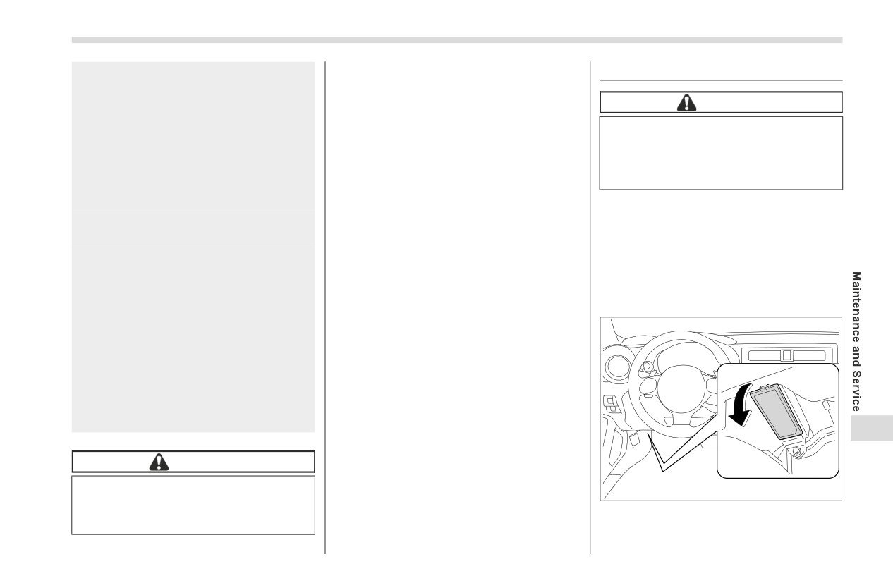
One is located under the instrument panel
it will shorten battery life.
behind the fuse box cover on the driver’s
seat side. To remove the cover, pull it out.
- CONTINUED -
372
Fuses
1
2
1
B02118
B01008
B00975
1) Fuse puller
1) Good
4. Pull out the fuse with the fuse puller.
2) Blown
5. Inspect the fuse. If it has blown,
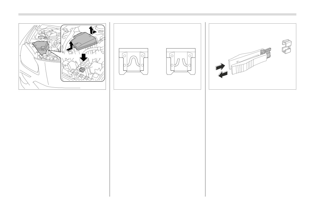
The other one (main fuse box) is housed
replace it with a spare fuse of the same
in the engine compartment. Also, the fuse
If any lights, accessories or other elec-
rating.
puller are stored in the fuse box.
trical controls do not operate, inspect the
6. If the same fuse blows again, this indi-
Pinch the upper part of the fuse puller
corresponding fuse. If a fuse has blown,
cates that its system has a problem.
when removing it from the main fuse box.
replace it.
Contact your SUBARU dealer for repairs.
1. Turn the ignition switch to the “OFF”
position and turn off all electrical accesso-
ries.
2. Remove the fuse box cover.
3. Determine which fuse may be blown.
Look at the back side of each fuse box
cover.
Installation of Accessories
373
11-27. Installation of Acces-
11-28. Replacing Bulbs
■ Headlights
sories
WARNING
Always consult your SUBARU dealer
before installing fog lights or any other
Bulbs may become very hot while
electrical equipment in your vehicle. Such
illuminated. Before replacing bulbs,
accessories may cause the electronic
turn off the lights and wait until the
system to malfunction if they are incor-
bulbs cool down, Otherwise, there
rectly installed or if they are not suited for
is the risk of sustaining a burn
the vehicle. We recommend that you
injury.
install only genuine SUBARU accessories
on your vehicle.
CAUTION
B02119
Before replacing a backup light,
stop the engine and allow the
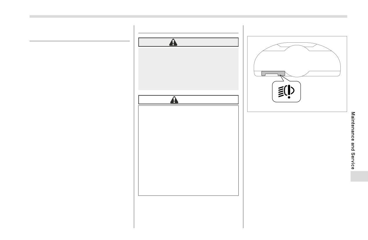
The LED headlight warning light illumi-
exhaust pipes and surrounding
nates if the LED headlights malfunction.
parts to cool sufficiently. As the
Have your vehicle inspected at a
bulbs are near the exhaust pipes,
SUBARU dealer as soon as possible.
there is a risk of being burned.
Replace any bulb only with a new
■ Backup Light
bulb of the specified wattage.
Using a bulb of different wattage
NOTE
could result in a fire. For the spec-
It may be difficult to replace the
ified wattage of each bulb, refer to
bulbs. We recommend that you have
"Bulb Chart" ) P387. For replace-
11
the bulbs replaced by your SUBARU
ment, contact your SUBARU
dealer if necessary.
dealer.
If a genuine SUBARU accessory has
been installed to the rear bumper,
check the manual included with the
accessory.
- CONTINUED -
374
Replacing Bulbs
■ Other Bulbs
It may be difficult to replace the bulbs.
We recommend that you have the
bulbs replaced by your SUBARU dealer
if necessary.
■ Adjusting Headlight Aim
B02120
B02122
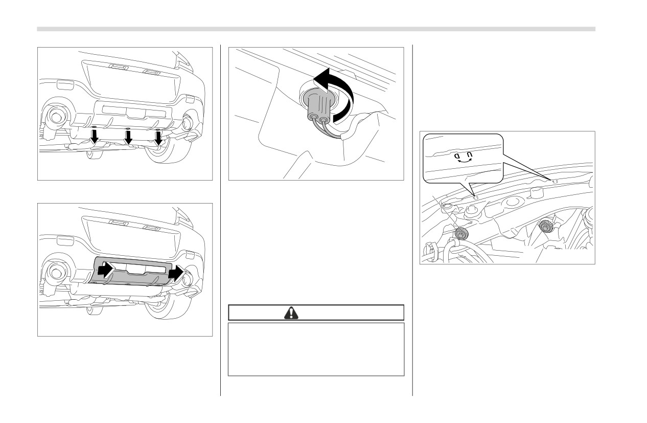
3. Turn the bulb socket counterclockwise
1.
Remove the clips.
2
and remove it.
4. Pull the bulb out of the bulb socket and
replace it with a new one.
5. Install the bulb socket by turning it
clockwise.
1
6. Reconnect the electrical connector.
B02156
7. Reinstall the rear bumper cover.
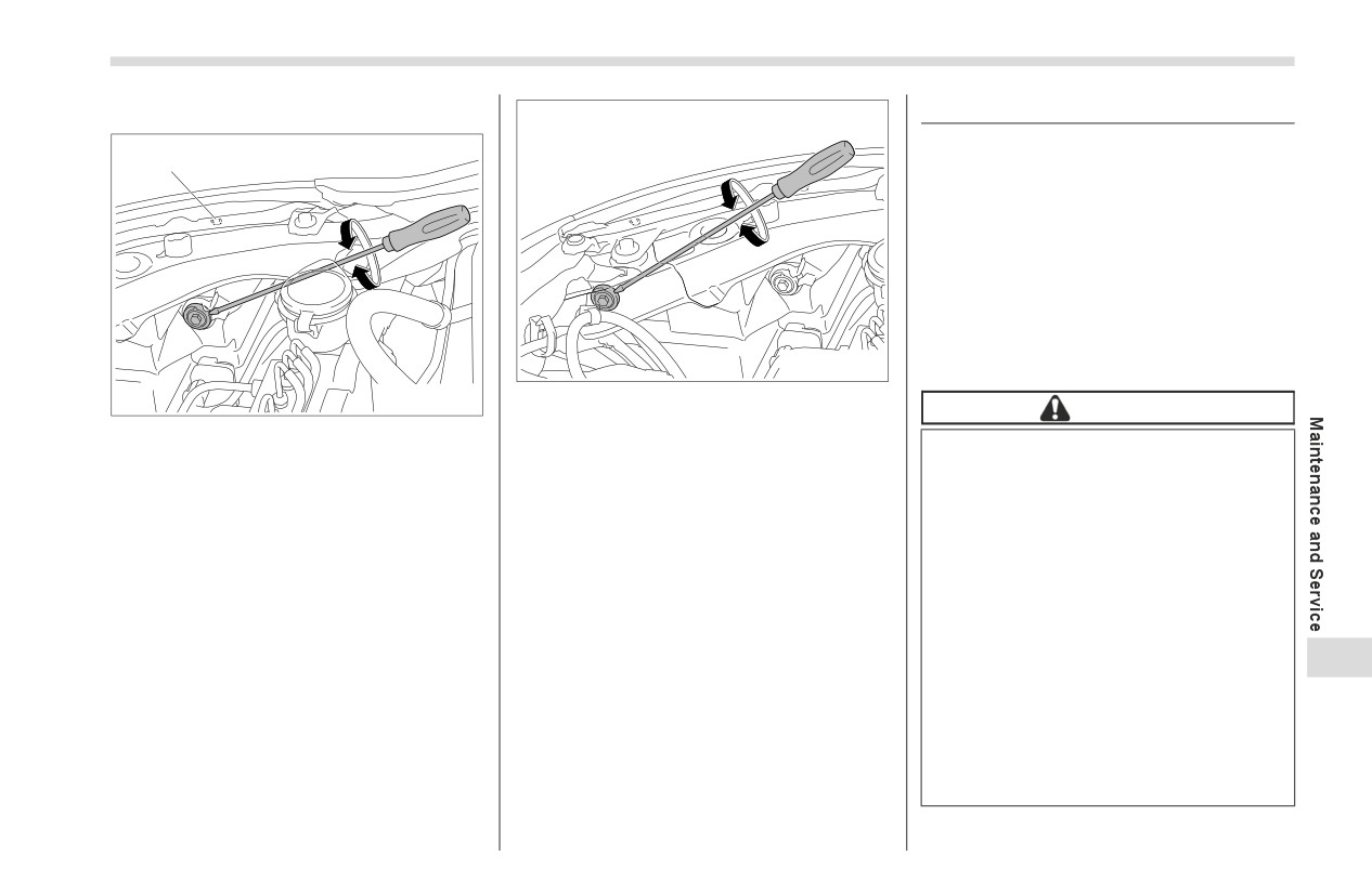
1) Adjustment bolt A
2) Adjustment bolt B
■ Trunk Light
▼ Before checking the headlight
aiming
CAUTION
B02121
1. Make sure the vehicle has a full tank of
Replacing the bulb could cause
gasoline and the area around the head-
2.
Remove the rear bumper cover.
burns since the bulb may be very
light is not deformed.
hot. Have the bulb replaced by your
SUBARU dealer.
2. Park the vehicle on level ground.
3. Sit in the driver’s seat.
4. Bounce the vehicle several times.
Replacing Battery
375
▼ Headlight aim adjustment
11-29. Replacing Battery
The access key fob may be discharged
1
under the following conditions.
The operation of the keyless access
function is unstable
The operating distance of the remote
keyless entry system is unstable
The transmitter does not operate prop-
erly when used within the standard
distance
B02158
Replace the battery with a new one.
B02157
2. Turn bolt B the same number of turns
CAUTION
and in the same direction as step 1.
1) Adjustment direction mark
Do not let dust, oil or water get on
1. Turn the bolt A clockwise or
NOTE
or in the access key fob/trans-
counterclockwise to adjust it. Remember
If the headlight aim cannot be
mitter when replacing battery.
the direction of the rotation and number of
adjusted, contact your SUBARU
Be careful not to damage the
rotations.
dealer.
printed circuit board in the
To inspect of the headlight aim posi-
access key fob/transmitter when
tion, consult a SUBARU dealer.
replacing the battery.
Be careful not to allow children to
touch the battery and any
removed parts; children could
11
swallow them.
There is a danger of an explosion
if
the battery is incorrectly
replaced. Replace only with the
same or equivalent type of the
battery.
- CONTINUED -
376
Replacing Battery
Batteries shall not be exposed to
Before replacing the battery,
excessive heat such as bright
remove any static electricity.
sunlight, fire or the like.
Battery: Button
battery
CR2032
or
NOTE
equivalent
Replace only with the same or
equivalent type of battery recom-
mended by the manufacturer.
1
Dispose of used batteries according
to the local laws.
Mount the battery in the correct
B01977
orientation to prevent fluid leakage. Be
careful not to bend the terminals. It
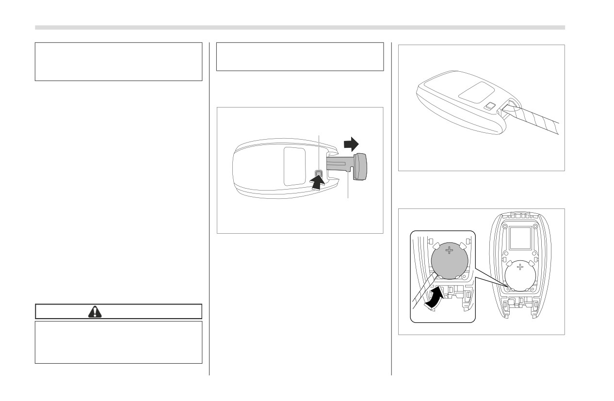
2. Wrap a flat-head screwdriver with vinyl
may result in a malfunction.
tape or a cloth, and insert it in the gap to
It is recommended that the battery
remove the cover.
2
should be replaced by a SUBARU
dealer.
202500
Use a new battery.
After replacing the battery, confirm
1)
Release button
that the access key fob/transmitter
2)
Emergency key
functions properly.
1. Take out the emergency key.
■ Replacing Battery of Access
Key Fob
CAUTION
When removing or fitting the
B01546
access key fob cover, make sure
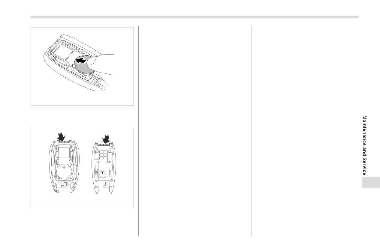
3. Take out the battery using a flat-head
that the plastic part does not
screwdriver with vinyl tape or a cloth.
come off or become misaligned.
Replacing Battery
377
B01547
4. Insert a new battery with its positive
(+) side facing upward as shown in the
figure.
11
B01542
5. Attach the cover to the access key fob
by fitting the projections and recesses
together.
Specifications
12-1. Specifications
380
12-2. Bulb Chart
387
Dimensions
380
Safety Precautions
387
Engine
380
Bulb Chart
388
Fuel
381
12-3. Vehicle Identification
390
Engine Oil
381
12-4. Function Settings
391
Manual Transmission and Differential Gear Oil
383
Function Settings and Adjustments on the Center
Fluids
383
Information Display
391
Engine Coolant
384
Individual Settings and Adjustments Excluding
Electrical System
385
Center Information Display and Combination
Tires
385
Meter Display (Color TFT)
391
Brake Pedal
385
Function Settings and Adjustments Performed
Brake Disc
386
by a Dealer
391
Brake Pad
386
12
380
Specifications
12-1. Specifications
These specifications are subject to change without notice.
■ Dimensions
in (mm)
Item
Dimensions
Drive system
RWD
Transmission type
AT
MT
Overall length
167.9 (4265)
Overall width
69.9 (1775)
Overall height
51.6 (1310)
Wheelbase
101.4 (2575)
Front
59.8 (1520)
Tread
Rear
61.0 (1550)
Ground clearance*1
5.1 (130)
*1: Measured with vehicle empty
AT: Automatic transmission
MT: Manual transmission
RWD: Rear Wheel Drive
■ Engine
Engine model
FA24 (2.4 L, DOHC, non-turbo)
Horizontally opposed, liquid cooled 4 cylinder,
Engine type
4-stroke gasoline engine
Displacement cu-in (cc)
146 (2,387)
Bore × Stroke in (mm)
3.70 × 3.39 (94.0 × 86.0)
Specifications
381
Engine model
FA24 (2.4 L, DOHC, non-turbo)
Compression ratio
12.5 : 1
Firing order
1 - 3 - 2 - 4
■ Fuel
Fuel requirement*1
Unleaded gasoline with 93 AKI (98 RON) or higher
Fuel tank capacity
13.2 US gal (50 liters, 11.0 Imp gal)
*1: For details, refer to "Fuel" ) P223.
■ Engine Oil
For the checking, adding and replacing procedure or other details, refer to "Engine Oil" ) P346.
NOTE
The procedure for changing the engine oil and oil filter should be performed by a properly-trained expert. It is recom-
mended that you have this service performed by your SUBARU dealer.
▼ Approved engine oil
Always use the SUBARU approved engine oil. For further details, please contact your SUBARU dealer.
If the approved engine oil is unavailable, use the alternative engine oil described on the next page.
▼ Alternative engine oil
If the SUBARU approved oil is unavailable, the following alternative oil can be used.
12
NOTE
Each quantity indicated is only a guideline. The necessary quantity for replacement may differ slightly depending on the
temperature and other factors.
In choosing an oil, you want the proper quality and viscosity, as well as one that will enhance fuel economy. Oils of lower
viscosity provide better fuel economy. However, in hot weather, oil of higher viscosity is required to properly lubricate the
engine. The following table lists the recommended viscosities and applicable temperatures.
- CONTINUED -
382
Specifications
When adding oil, different brands may be used together as long as they are the same API classification and SAE viscosity
as those recommended by SUBARU.
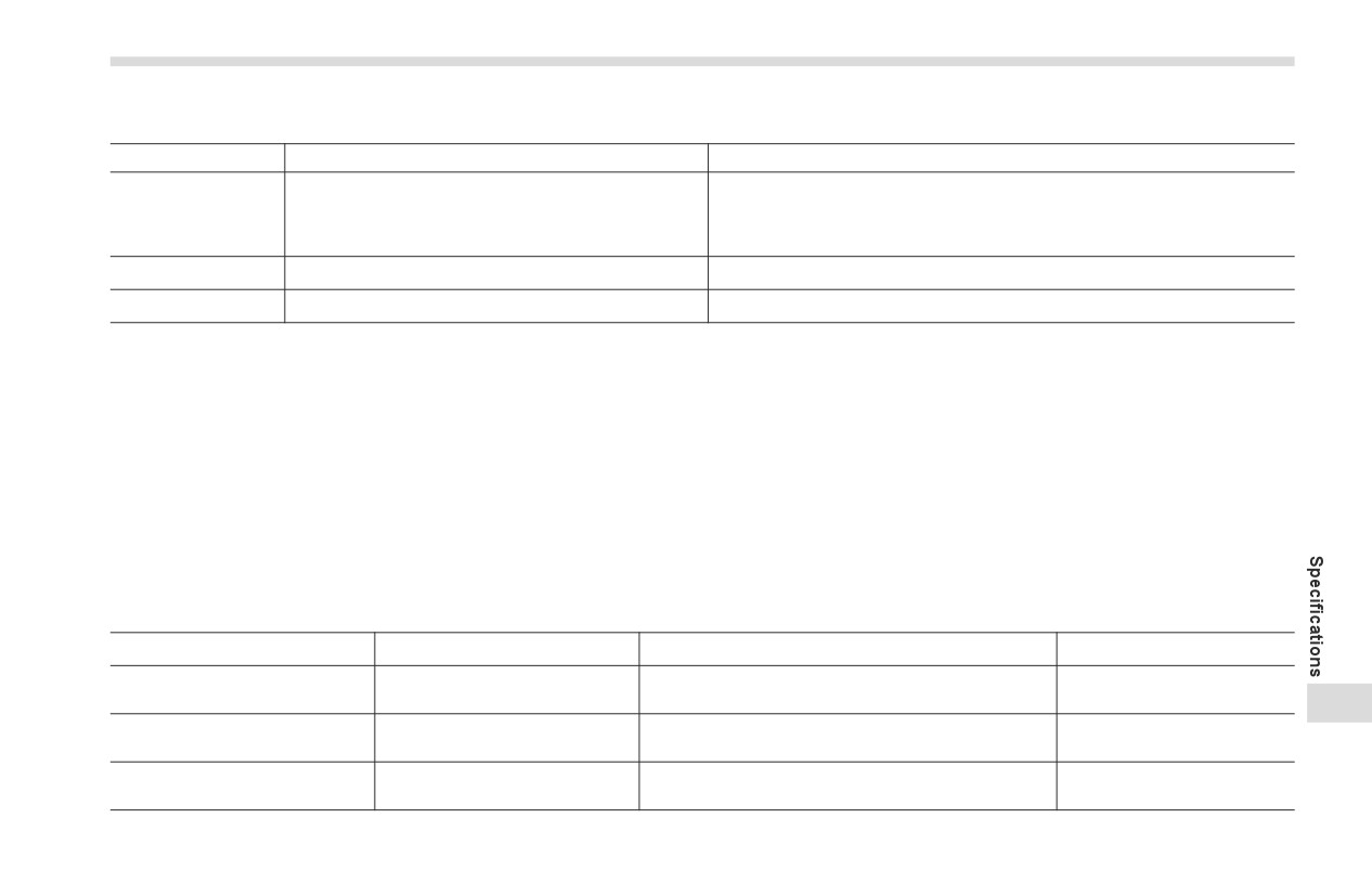
SAE viscosity No. and
Oil grade
Engine oil capacity
applicable temperature
0W-20 synthetic oil is the required oil
Adding the oil from low level to full
for optimum engine performance and
level:
protection. Conventional oil may be
1.1 US qt (1.0 liter, 0.9 Imp qt)
used if synthetic oil is unavailable.
Changing the oil:
*: If
0W-20 synthetic oil is not avail-
5.1 US qt (4.8 liters, 4.2 Imp qt)
able, 5W-30 conventional oil may
Changing the oil and oil filter:
be used if you need to add oil.
5.3 US qt (5.0 liters, 4.4 Imp qt)
However, you should change to
0W-20 synthetic oil at the next oil
change.
or
ZOM0886
ZOM0293
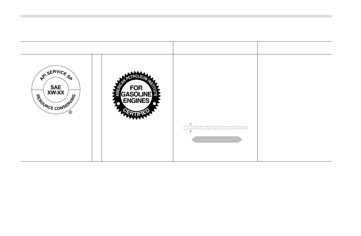
API (American Petroleum Insti-
tute) classification SN with the
ILSAC (International Lubricant
-30 -20 -10
0
10
20
30
40
words “RESOURCE CON-
Specification Advisory Commit-
-20
0
20
40
60
80
100
SERVING”, SN PLUS with the
tee) GF-5 or GF-6A which can
words “RESOURCE CON-
be identified with the ILSAC cer-
0W-20*
SERVING” or SP with the words
tification mark (Starburst mark)
“RESOURCE CONSERVING”
ZOM0294
Specifications
383
■ Manual Transmission and Differential Gear Oil
Oil
Manual transmission oil
Differential gear oil
Manual Transmission Gear Oil LV 75W*3
Differential Gear Oil LX*3
Oil grade
Other gear oil that meets API GL-5 SAE 75W-85 or GL-5 SAE 75W-
API GL-4 SAE 75W*4
90 specifications*5
Oil capacity*1
2.3 US qt (2.2 liters, 1.9 Imp qt)
1.22 US qt (1.15 liters, 1.01 Imp qt)
Remarks*2
"Manual Transmission Oil" ) P353
"Differential Gear Oil" ) P353
*1: The indicated oil quantity is only a guideline. The necessary quantity for replacement may differ slightly depending on the temperature and other
factors. After refilling the gearbox with oil, the oil level should be checked.
*2: For more details about maintenance and service, refer to the indicated section.
*3: The vehicle is filled at the factory.
*4: This type of manual transmission oil can be used. However, using this type of oil will increase fuel consumption.
If oil other than “Manual Transmission Gear Oil LV 75W” is used, the following may be experienced:
The overall performance and function of the transmission may be adversely affected.
Rattling noises may occur during idling and fuel consumption may increase.
Never use different brands together.
*5: Using a differential gear oil other than “Differential Gear Oil LX” may cause noise, vibrations and increased fuel consumption. Never use different
brands together.
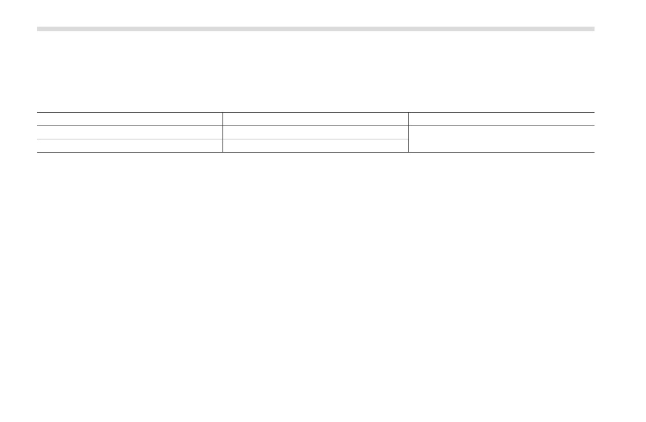
■ Fluids
Fluid
Fluid type*1
Fluid capacity*2
Remarks*3
Automatic Transmission Fluid
"Automatic Transmission
ATF WS
7.9 US qt (7.5 liters, 6.6 Imp qt)
(AT models)
Fluid" ) P352
12
FMVSS No. 116, DOT 3 or
Brake fluid
ʊ
"Brake Fluid" ) P353
DOT 4 brake fluid
FMVSS No. 116, DOT 3 or
"Clutch Fluid (MT models)"
Clutch fluid (MT models)
ʊ
DOT 4 brake fluid
) P354
- CONTINUED -
384
Specifications
*1: Use one of the indicated types of fluid.
*2: The indicated fluid quantity is only a guideline. The necessary quantity for replacement may differ slightly depending on the temperature and other
factors.
*3: For more details about maintenance and service, refer to the indicated section.
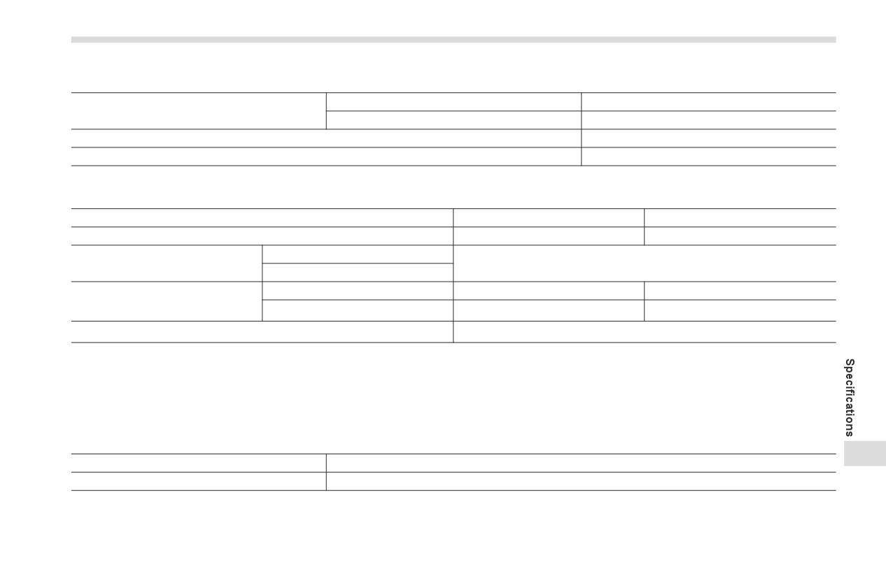
■ Engine Coolant
Vehicle model
Coolant capacity
Coolant type
AT models
8.1 US qt (7.7 liters, 6.8 Imp qt)
SUBARU SUPER COOLANT
MT models
7.8 US qt (7.4 liters, 6.5 Imp qt)
The indicated coolant quantity is only a guideline. The necessary quantity for replacement may differ slightly depending on the
temperature and other factors. For more details about maintenance and service, refer to "Cooling System" ) P348.
Specifications
385
■ Electrical System
U.S. spec and Canada spec models
75D23L
Battery type
Except U.S. spec and Canada spec models
55D23L
Alternator
12 V-150 A
Spark plugs
ZXE27HBR8 (DENSO)
■ Tires
Tire size
215/45R17 87W
215/40R18 85Y
Wheel size
17 × 7 1/2J
18 × 7 1/2J
Front
Pressure
35 psi (240 kPa, 2.4 kgf/cm2)
Rear
Size
ʊ
215/40R18 85Y
Spare tire*1
Pressure
ʊ
35 psi (240 kPa, 2.4 kgf/cm2)
Wheel nut tightening torque
88.5 lbf·ft (120 N·m, 12.2 kgf·m)*2
*1: If equipped
*2: This torque is equivalent to applying approximately 88 to 110 lbf (40 to 50 kgf) at the end of the wheel nut wrench. If you have tightened the wheel
nuts by yourself, have the tightening torque checked at the nearest automotive service facility as soon as possible. For the wheel nut tightening
procedure, refer to "Changing a Flat Tire" ) P303.
■ Brake Pedal
in (mm)
12
Pedal clearance
2.91 (74)*
Pedal free play
0.02 - 0.06 (0.5 - 1.5)
*: Minimum value when pedal is operated with a force of 67.4 lbf (300 N, 30.6 kgf) while the engine is running.
- CONTINUED -
386
Specifications
■ Brake Disc
If you need information on the usage limit value of brake discs and the method for measuring them, we recommend that you consult
your SUBARU dealer.
■ Brake Pad
in (mm)
Brake pad wear limit
0.06 (1.5)
Bulb Chart
387
12-2. Bulb Chart
■ Safety Precautions
WARNING
Bulbs may become very hot while
illuminated. Before replacing bulbs,
turn off the lights and wait until the
bulbs cool down. Otherwise, there
is a risk of sustaining a burn injury.
CAUTION
Replace any bulb only with a new
bulb of the specified wattage. Using
a bulb of different wattage could
result in a fire.
12
- CONTINUED -
388
Bulb Chart
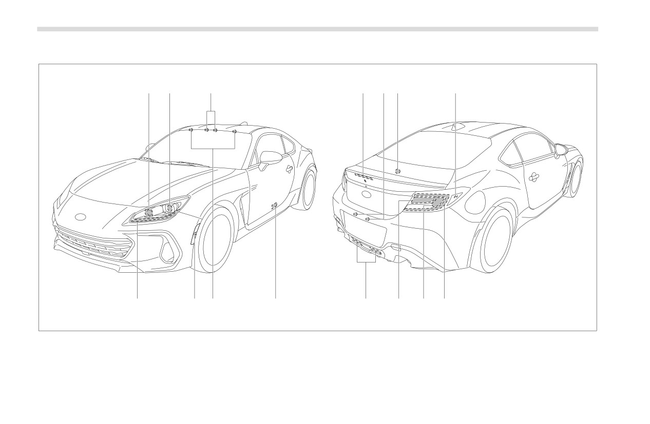
■ Bulb Chart
A
B
1
C
D
2
E
J
I
5
4
3
H
G
F
C00473
NOTE
Lights indicated by letters are the LED (Light Emitting Diode) type. Consult your SUBARU dealer for replacement.
Bulb Chart
389
Wattage
Bulb No.
1)
Map lights
12 V-8 W
ʊ
2)
Trunk light
12 V-3.8 W
SAE #194
3)
Backup lights
12 V-16 W
W16W
4)
Door step lights (If equipped)
12 V-5 W
W5W
5)
Vanity mirror lights (If equipped)
12 V-2 W
ʊ
A)
Front turn signal lights
ʊ
ʊ
B)
Low and high beam headlights
ʊ
ʊ
C)
High-mounted stop light
ʊ
ʊ
D)
License plate lights
ʊ
ʊ
E)
Rear side marker lights
ʊ
ʊ
F)
Tail and stop lights
ʊ
ʊ
G)
Stop lights
ʊ
ʊ
H)
Rear turn signal lights
ʊ
ʊ
I)
Front side marker lights
ʊ
ʊ
J)
Front position lights
ʊ
ʊ
Daytime running lights
ʊ
ʊ
12
- CONTINUED -
390
Vehicle Identification
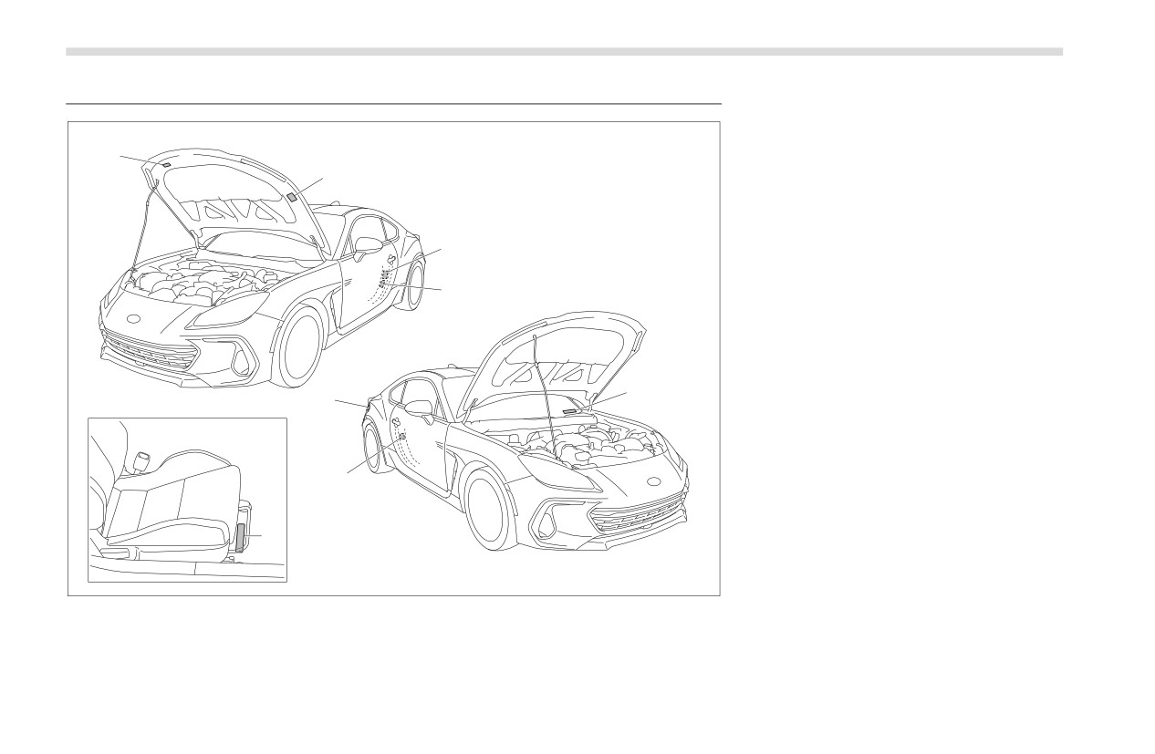
1) Vehicle identification number under the
12-3. Vehicle Identification
floor carpet of the right-hand front seat
2) Emission control label
3) Certification and bar code label
(if
8
equipped)
2
4) Tire inflation pressure label
(vehicle
placard)
5) Vehicle identification number label
6) Model number label (if equipped)
3,6
7) Fuel label
8) Air conditioner label
4
5
7
6
1
C00538
Function Settings
391
12-4. Function Settings
■ Function Settings and Adjustments on the Center Information Display
Setting adjustments can be manually changed within the center information display to meet your personal requirements. Refer to
"Center Information Display (CID)" ) P160.
■ Individual Settings and Adjustments Excluding Center Information Display and Combination Meter
Display (Color TFT)
For setting adjustments to the following items, refer to the appropriate page for details.
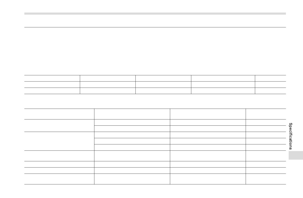
Item
Function
Available settings
Factory default setting
Page
Alarm system
Alarm system
Operation/Non-operation
Non-operation
115
Remote keyless entry system
Audible signal
Operation/Non-operation
Operation
110
■ Function Settings and Adjustments Performed by a Dealer
Factory default set-
Item
Function
Available settings
ting
Audible signal volume
Level 1 to 7
Level 5
Keyless access with push-button
Trunk open without key
ON/OFF
ON
Remote keyless entry system
Operation/Non-operation
Operation
Remote keyless entry system
Panic function
Operation/Non-operation
Operation
Vehicle finder function
Operation/Non-operation
Operation
Operation of trunk opening by access key
Non-operation/Pressing twice/Pressing
Remote trunk open function*1
Pressing and holding
12
fob
and holding
Key lock-in prevention
Key lock-in prevention
Operation/Non-operation
Operation
Battery drainage prevention function
Battery drainage prevention function
Operation/Non-operation
Operation
Sensitivity of the operation of the auto
Auto dimmer cancel
OFF/Min/Low/Mid/Hi/Max
Mid
dimmer cancel
- CONTINUED -
392
Function Settings
Factory default set-
Item
Function
Available settings
ting
Daytime running light system*2
Daytime running light system
Operation/Non-operation
Operation
High beam assist function*1
High beam assist function
Operation/Non-operation
Operation
Operation when the doors are unlocked
Operation/Non-operation
Operation
Operation after the engine switch is
Operation/Non-operation
Operation
Illumination
turned off
Interior light illumination upon approach
Operation/Non-operation
Operation
Interior light illumination
Operation/Non-operation
Operation
Active sound control
Active sound control
Operation/Non-operation
Operation
*1: If equipped
*2: For U.S. spec. models
Consumer Information and Reporting Safety Defects
13-1. For U.S.A
394
13-3. Uniform Tire Quality Grading Standards
405
13-2. Tire Information
394
TREADWEAR
405
Tire Labeling
394
TRACTION AA, A, B, C
405
Recommended Tire Inflation Pressure
396
TEMPERATURE A, B, C
406
Glossary of Tire Terminology
397
13-4. Reporting Safety Defects (USA)
406
Tire Care - Maintenance and Safety Practices
401
13-5. How to Contact Transport Canada in
Vehicle Load Limit - How to Determine
402
Order to Report a Safety Concern Relating
Determining Compatibility of Tire and Vehicle
to the Vehicle (Canada)
407
Load Capacities
404
Adverse Safety Consequences of Overloading on
Handling and Stopping and on Tires
404
Steps for Determining Correct Load Limit
404
13
394
For U.S.A.
13-1. For U.S.A.
13-2. Tire Information
Example:
The following information has been
■ Tire Labeling
P
205 / 60 R
16
compiled according to Code of Federal
Many markings (e.g. Tire size, Tire
(1)
(2)
(3)
(4)
(5)
Regulations “Title 49, Part 575”.
Identification Number or TIN) are
(1) P = Certain tire type used on
placed on the sidewall of a tire by
light
duty vehicles such as
tire manufacturers. These marking
passenger cars
can provide you with useful informa-
(2) Section Width in millimeters
tion on the tire.
(3) Aspect Ratio (= section height ÷
section width).
▼ Tire size
(4) R = Radial Construction
Your vehicle comes equipped with
(5) Rim diameter in inches
P-Metric tire size. It is important to
understand the sizing system in
▽ Load and Speed Rating Descrip-
selecting the proper tire for your
tions
vehicles. Here is a brief review of
The load and speed rating descrip-
the tire sizing system with a break-
tions will appear following the size
down of its individual elements.
designation.
▽ P Metric
They provide two important facts
about the tire. First, the number
With the P-Metric system, Section
designation is its load index.
Width is measured in millimeters.
Second, the letter designation indi-
To convert millimeters into inches,
cates the tire’s speed rating.
divide by 25.4. The Aspect Ratio
Example:
(Section Height divided by Section
Width) helps provide more dimen-
P
205 / 60 R
16
91 V
sional information about the tire
Size designation
(6)
(7)
size.
Tire Information
395
(6) Load Index: A numerical code
WARNING
DOT XX XX XXX XXXX
which specifies the maximum load a
(1)
(2)
(3)
(4)
(5)
tire can carry at the speed indicated
Speed ratings apply only to
by its speed symbol, at maximum
the tire, not to the vehicle.
(1) DOT symbol*
inflation pressure.
Putting a speed rated tire on
(2) Manufacturer’s Identification
any vehicle does not mean
For example, “91” means 1,356 lbs
Mark
the vehicle can be operated
(615 kg), “90” means 1,323 lbs (600 kg),
(3) Tire Size Code
at the tire’s rated speed.
“89” means 1,279 lbs (580 kg)
(4) Tire Type Code
The speed rating is void if
(5) Date of Manufacture
WARNING
the tires are worn out,
The first two figures identify the
damaged,
repaired,
Load indices apply only to the
week, starting with “01” to represent
retreaded, or otherwise
tire, not to the vehicle. Putting
the first full week of the calendar
altered from their original
a load rated tire on any vehicle
year; the second two figures repre-
condition. If tires are
does not mean the vehicle can
sent the year. For example, 0101
repaired, retreaded, or other-
be loaded up to the tire’s rated
means the 1st week of 2001.
wise altered, they may not be
load.
suitable for original equip-
*: The DOT symbol certifies that the
ment tire designed loads and
tire
conforms to applicable
(7) Speed Rating: An alphabetical
Federal Motor Vehicle Safety
speeds.
system describing a tire’s capability
Standards.
to travel at established and prede-
▼ Tire Identification Number
termined speeds.
▼ Other markings
(TIN)
For example, “V” means 149 mph
The following makings are also
Tire Identification Number (TIN) is
(240 km/h)
placed on the sidewall.
marked on the intended outboard
sidewall. The TIN is composed of
13
four groups. Here is a brief review of
the TIN with a breakdown of its indi-
vidual elements.
- CONTINUED -
396
Tire Information
▽ Maximum permissible infla-
▽ Construction
▼ Vehicle placard
tion pressure
The generic name of each cord
The maximum cold inflation pres-
material used in the plies
(both
sure to which this tire may be
sidewall and tread area) of this tire.
inflated. For example, “350 kPa (51
For example,
“PLIES: TREAD
2
PSI) MAX. PRESS”
STEEL
+
2 POLYESTER
+
1
NYLON SIDEWALL
2 POLY-
▽ Maximum load rating
ESTER”
The load rating at the maximum
permissible weight load for this tire.
▽ Uniform Tire Quality
For example, “MAX. LOAD 615 kg
Grading (UTQG)
B02109
(1,356 LBS) @ 350 kPa (51 PSI)
For details, refer to "Uniform Tire
MAX. PRESS.”
Quality Grading Standards" ) P405.
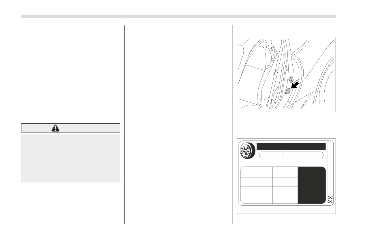
The vehicle placard is affixed to the
driver’s side B-pillar.
WARNING
■ Recommended Tire Inflation
Example:
Pressure
Maximum load rating applies
TIRE AND LOADING INFORMATION
only to the tire, not to the vehi-
▼ Recommended cold tire infla-
RENSEIGNEMENTS SUR LES PNEUS ET LE CHARGEMENT
cle. Putting a load rated tire on
tion pressure
SEATING CAPACITY
TOTAL X
FRONT
X
REAR
X
NOMBRE DE PLACES
AVANT
ARRI¨RE
The combined weight of occupants and cargo should never exceed XXXkg or XXXlbs.
any vehicle does not mean the
For the recommended cold tire infla-
Le poids total des occupants et du chargement ne doit jamais dØpasser XXXkg ou XXXlb.
vehicle can be loaded up to
COLD TIRE PRESSURE
tion pressure for your vehicle’s tires,
TIRE
SIZE
SEE OWNER S
PRESSION DES
PNEU
DIMENSIONS
MANUAL FOR
the tire’s rated load.
PNEUS FROID
refer to "Tires" ) P385.
ADDITIONAL
FRONT
PXXX/XXRXX
XXXKPA, XXPSI
INFORMATION
AVANT
REAR
PXXX/XXRXX
XXXKPA, XXPSI
VOIR LE MANUEL
▽ Construction type
ARRI¨RE
DE L USAGER
SPARE
POUR PLUS DE
TXXX/XXDXX
XXXKPA, XXPSI
RENSEIGNEMENTS
Applicable construction of this tire.
DE SECOURS
For example, “TUBELESS STEEL
D00155
BELTED RADIAL”
Tire Information
397
The vehicle placard shows original
adjust the tire pressures to the
by ply cords and that is shaped to fit
tire size, recommended cold tire
specific values. Driving even a short
the rim.
inflation pressure on each tire at
distance warms up the tires and
Bead separation
maximum loaded vehicle weight,
increases the tire pressures. Also,
A breakdown of the bond between
seating capacity and loading infor-
the tire pressures are affected by
components in the bead.
mation.
the outside temperature. It is best to
check tire pressure outdoors before
Bias ply tire
▼ Adverse safety consequences
driving the vehicle. When a tire
A pneumatic tire in which the ply
of under-inflation
becomes warm, the air inside it
cords that extend to the beads are
Driving at high speeds with exces-
expands, causing the tire pressure
laid at alternate angles substantially
to increase. Be careful not to
less than
90 degrees to the
sively low tire pressures can cause
the tires to flex severely and to
mistakenly release air from a warm
centerline of the tread.
tire to reduce its pressure.
rapidly become hot. A sharp
Carcass
increase in temperature could
The tire structure, except tread and
■ Glossary of Tire Terminology
cause tread separation, and failure
sidewall rubber which, when
Accessory weight
of the tire(s). Possible resulting loss
inflated, bears the load.
of vehicle control could lead to an
The combined weight (in excess of
Chunking
accident.
those standard items which may be
replaced) of automatic transmis-
The breaking away of pieces of the
▼ Measuring and adjusting air
sion, power steering, power brakes,
tread or sidewall.
pressure to achieve proper
power windows, power seats, radio,
Cold tire pressure
inflation
and heater, to the extent that these
The pressure in a tire that has been
items are available as factory-
Check and, if necessary, adjust the
driven less than 1 mile or has been
installed
equipment
(whether
pressure of each tire (including the
standing for three hours or more.
installed or not).
spare) at least once a month and
Cord
13
before any long journey. Check the
Bead
The strands forming the plies in the
tire pressures when the tires are
The part of the tire that is made of
tire.
cold. Use a pressure gauge to
steel wires, wrapped or reinforced
- CONTINUED -
398
Tire Information
Cord separation
contains the inflating medium within
Maximum inflation pressure
The parting of cords from adjacent
the tire.
The maximum cold inflation pres-
rubber compounds.
Innerliner separation
sure to which a tire may be inflated.
Cracking
The parting of the innerliner from
Maximum load rating
Any parting within the tread,
cord material in the carcass.
The load rating for a tire at the
sidewall, or inner liner of the tire
Intended outboard sidewall
maximum permissible inflation pres-
extending to cord material.
sure for that tire.
(1) The sidewall that contains a
Curb weight
whitewall, bears white lettering or
Maximum loaded vehicle
The weight of a motor vehicle with
bears manufacturer, brand, and/
weight
standard equipment including the
or model name molding that is
The sum of:
maximum capacity of fuel, oil and
higher or deeper than the same
(a) Curb weight
coolant, and if so equipped, air
molding on the other sidewall of
(b) Accessory weight
conditioning and additional weight
the tire, or
(c) Vehicle capacity weight
optional engine.
(2) The outward facing sidewall
(d) Production options weight
of an asymmetrical tire that has a
Extra load tire
Maximum permissible inflation
particular side that must always
A tire designed to operate at higher
pressure
face outward when mounting on a
loads and higher inflation pressure
The maximum cold inflation pres-
vehicle.
than the corresponding standard
sure to which a tire may be inflated.
Light truck (LT) tire
tire.
A tire designated by its manufac-
Measuring rim
Groove
turer as primarily intended for use
The rim on which a tire is fitted for
The space between two adjacent
on lightweight trucks or multipur-
physical dimension requirements.
tread ribs.
pose passenger vehicles.
Normal occupant weight
Innerliner
Load rating
150 lbs (68 kg) times the number of
The layer(s) forming the inside
The maximum load that a tire is
occupants specified in the second
surface of a tubeless tire that
rated to carry for a given inflation
column of Table 1 that is appended
pressure.
to the end of this section.