Subaru Legacy III (2000-2003 year). Manual - part 880


  Index      Subaru     Subaru Legacy III - service repair manual 2000-2003 year


Search            


Content   ..  878  879  880  881   ..


Subaru Legacy III (2000-2003 year). Manual - part 880


AC-56

HVAC SYSTEM (AUTO A/C) (DIAGNOSTICS)

DIAGNOSTIC PROCEDURE WITH DIAGNOSTIC TROUBLE CODE (DTC) (LHD 

MODEL)

D: DTC 25 OR –25 (SUNLOAD SENSOR)

TROUBLE SYMPTOM:
• Sensor identified that sunlight is at maximum. Then, A/C system is controlled to COOL side.
• Sensor identified that sunlight is at minimum. Then, A/C system is controlled to HOT side.

NOTE:
When the sunload sensor is checked inside the passenger compartment or in the shade, DTC “25” may ap-
pear on the indicator. Always check the sunload sensor in a place where it senses direct sunlight.
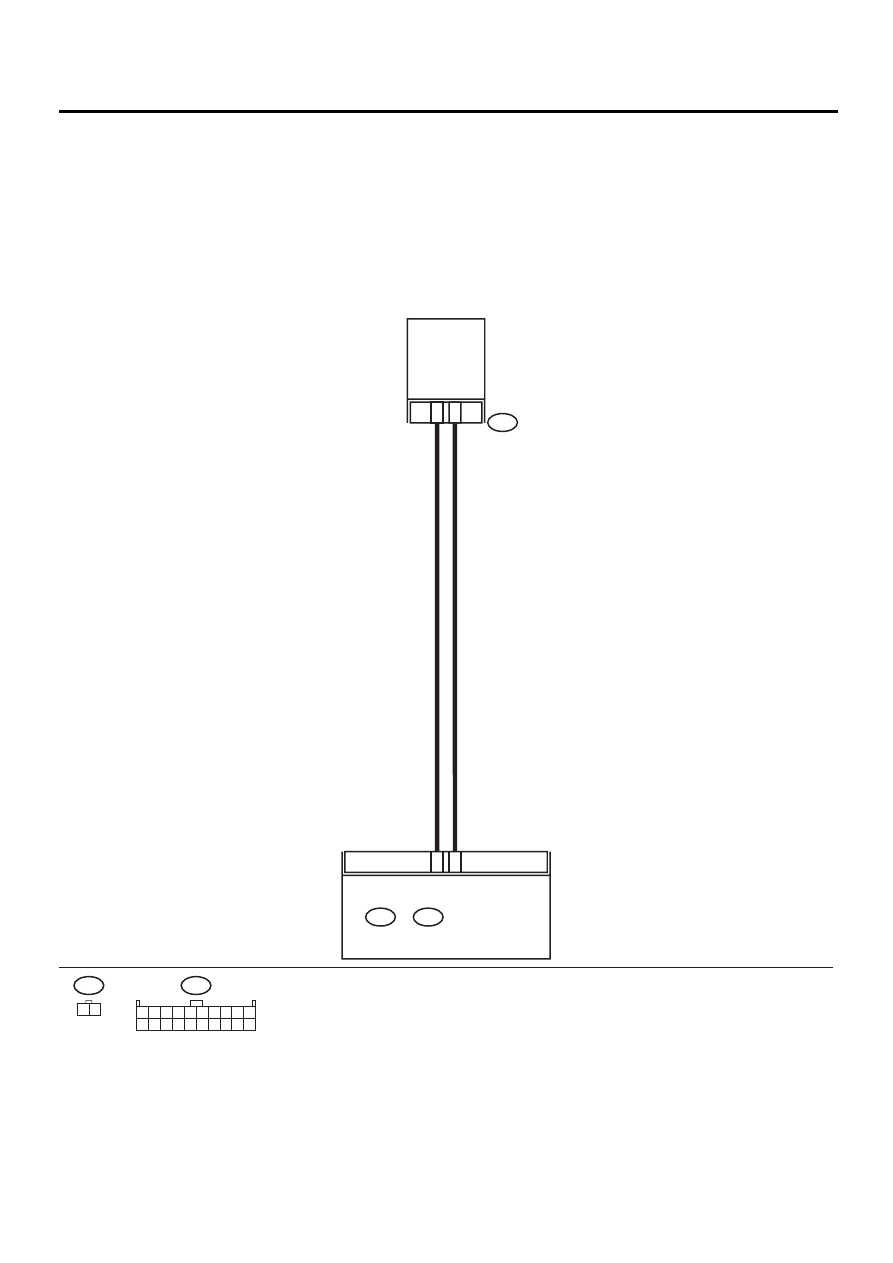
WIRING DIAGRAM:

AC-00324

i51

SUNLOAD

SENSOR

i51

1 2

i49

B:

1 2 3 4 5 6 7 8 9 10

11 12 13 14 15 16 17 18 19 20

i49

B:

i48

A:

AUTO A/C

CONTROL MODULE

B17

B16

1

2

AC-57

HVAC SYSTEM (AUTO A/C) (DIAGNOSTICS)

DIAGNOSTIC PROCEDURE WITH DIAGNOSTIC TROUBLE CODE (DTC) (LHD 

MODEL)

Step

Value

Yes

No

1

CHECK INPUT VOLTAGE TO SUNLOAD 
SENSOR.
1) Turn ignition switch to OFF.
2) Remove sunload sensor. <Ref. to AC-48, 

REMOVAL, Sunload Sensor (Auto A/C).> 

3) Turn ignition switch to ON.
4) Measure input voltage to sunload sensor.

Connector & terminal

(i51) No. 2 (+) — No. 1 (

−−−−

):

Is the measured value the same as speci-
fied value?

Approx. 4.2 V

Go to step 4.

Go to step 2.

2

CHECK HARNESS CONNECTOR BETWEEN 
A/C CONTROL MODULE AND SUNLOAD 
SENSOR.
1) Turn ignition switch to OFF.
2) Disconnect connectors from A/C control 

module.

3) Measure resistance of harness between A/

C control module and sunload sensor.

Connector & terminal

(i51) No. 2 — (i49) No. 16:

Is the measured value less than the speci-
fied value?

Go to step 3.

Repair harness 
between A/C con-
trol module and 
sunload sensor.

3

CHECK HARNESS CONNECTOR BETWEEN 
A/C CONTROL MODULE AND SUNLOAD 
SENSOR.
Measure resistance of harness between A/C 
control module and sunload sensor.

Connector & terminal

(i51) No. 1 — (i49) No. 17:

Is the measured value less than the specified 
value?

Go to step 4.

Repair harness 
between A/C con-
trol module and 
sunload sensor.

4

CHECK VOLTAGE OF INPUT SIGNAL TO A/
C CONTROL MODULE.
1) Connect connectors to A/C control module 

and sunload sensor.

2) Turn ignition switch to ON.
3) Measure voltage between A/C control mod-

ule connectors.

Connector & terminal

(i49) No. 16 (+) — No. 17 (

−−−−

):

Is the measured value the same as speci-
fied value?

Approx. 2.5 V

Go to step 5.

Replace sunload 
sensor.

5

CHECK POOR CONTACT.
Check poor contact in A/C control module con-
nector.
Is there poor contact in connector?

There is no poor contact.

Replace A/C con-
trol module.

Repair connector.

AC-58

HVAC SYSTEM (AUTO A/C) (DIAGNOSTICS)

DIAGNOSTIC PROCEDURE WITH DIAGNOSTIC TROUBLE CODE (DTC) (LHD 

MODEL)

E: DTC 31, 32, 33, 34 OR 35 (MODE DOOR ACTUATOR)

TROUBLE SYMPTOM:
Air flow outlet is not changed.
WIRING DIAGRAM:

AC-00372

B77

A:

i48

1 2 3 4 5 6 7 8
9 10 11 12 13 14 15 16

B77

i40

B201

4

7

1

2

10

8

9

5

6

A6

A5

A1

A2

A10

A9

1 2 3 4 5 6 7 8 9 10

A:

i48

B:

i49

AUTO A/C 
CONTROL
MODULE

MODE ACTUATOR

6

5

3

1

2

4

i40

1 2

3 4

5

8

10

9

6 7

AC-59

HVAC SYSTEM (AUTO A/C) (DIAGNOSTICS)

DIAGNOSTIC PROCEDURE WITH DIAGNOSTIC TROUBLE CODE (DTC) (LHD 

MODEL)

Step

Value

Yes

No

1

CHECK POWER SUPPLY FOR AUTO A/C 
CONTROL MODULE SIDE.
1) Turn the ignition switch to ON.
2) Press the mode switch to VENT position.
3) Press the DEF switch and measure the 

voltage between auto A/C control module 
and chassis ground when VENT is 
changed to DEF position.

Connector & terminal

(i48) No. 6 (+) — Chassis ground (

−−−−

):

Is the measured value more than specified 
value?

12 V

Go to step 2.

Replace the auto 
A/C control mod-
ule.

2

CHECK POWER SUPPLY FOR ACTUATOR 
SIDE.
1) Press the mode switch to VENT position.
2) Press the DEF switch and measure the 

voltage between mode door actuator har-
ness connector and chassis ground when 
VENT is changed to DEF position.

Connector & terminal

(B77) No. 2 (+) — Chassis ground (

−−−−

):

Is the measured value more than specified 
value?

7 V (At normal temperature)

Go to step 3.

Repair the har-
ness between auto 
A/C control mod-
ule and mode door 
actuator.

3

CHECK POWER SUPPLY FOR AUTO A/C 
CONTROL MODULE SIDE.
1) Press the DEF switch.
2) Press the mode switch to VENT position 

and measure the voltage between auto A/C 
control module and chassis ground when 
DEF is changed to VENT position.

Connector & terminal

(i48) No. 5 (+) — Chassis ground (

−−−−

):

Is the measured value more than specified 
value?

12 V

Go to step 4.

Replace the auto 
A/C control mod-
ule.

4

CHECK POWER SUPPLY FOR ACTUATOR 
SIDE.
1) Press the DEF switch.
2) Press the mode switch to VENT position 

and measure the voltage between mode 
door actuator harness connector and chas-
sis ground when DEF is changed to VENT 
position.

Connector & terminal

(B77) No. 1 (+) — Chassis ground (

−−−−

):

Is the measured value more than specified 
value?

7 V (At normal temperature)

Go to step 5.

Repair the har-
ness between auto 
A/C control mod-
ule and mode door 
actuator.

5

CHECK ACTUATOR.
1) Turn the ignition switch to OFF.
2) Disconnect the connector from mode door 

actuator.

3) Connect the battery positive (+) terminal to 

terminal No. 1 and ground (

) terminal to 

terminal No. 2 of mode door actuator to 
make sure that actuator operates.

4) Connect the battery positive (+) terminal to 

terminal No. 2 and ground (

) terminal to 

terminal No. 1 of mode door actuator to 
make sure that actuator operates.
Does the motor operate normally?

The motor operates normally.

Go to step 6.

Replace the mode 
door actuator.


Content   ..  878  879  880  881   ..