Subaru Legacy III (2000-2003 year). Manual - part 684


  Index      Subaru     Subaru Legacy III - service repair manual 2000-2003 year


Search            


Content   ..  682  683  684  685   ..


Subaru Legacy III (2000-2003 year). Manual - part 684


DS-14

DRIVE SHAFT SYSTEM

PROPELLER SHAFT

2. Propeller Shaft

A: REMOVAL

NOTE:
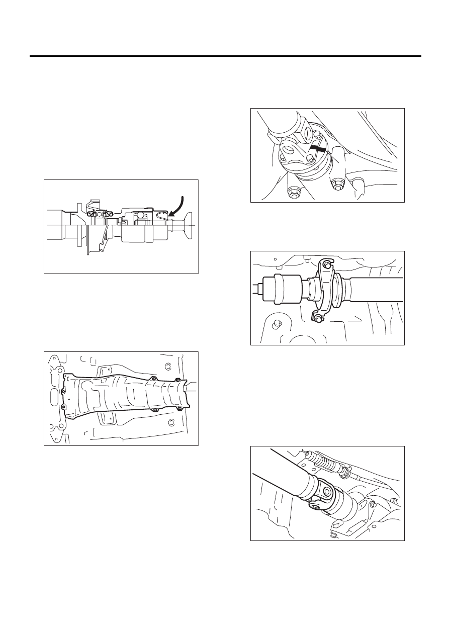
• Before removing propeller shaft, wrap metal
parts with a cloth or rubber material.
• In case of DOJ type, before removing propeller
shaft, wrap metal parts (installed at the rubber boot
of center DOJ) with a cloth or rubber material, as
shown in the figure. Rubber boot may be damaged
due to interference with adjacent metal parts while
bending the DOJ during removal.

1) Disconnect ground cable from battery.
2) Move select lever or gear shift lever to “N”.
3) Release the parking brake.
4) Jack-up vehicle and support it with sturdy racks.
5) Remove center exhaust pipes.
6) Remove rear exhaust pipe and muffler.
7) Remove heat shield cover.

8) Put matching marks on propeller shaft and rear
differential.

9) Remove the four bolts which hold propeller shaft
to rear differential.

NOTE:
Remove all but one bolt.

10) Remove the two bolts which hold center bear-
ing to vehicle body.

11) Remove propeller shaft from transmission.

CAUTION:
Be sure not to damage oil seals and the friction-
al surface of sleeve yoke.

NOTE:
• Be sure to use an empty oil can to catch oil flow-
ing out when removing propeller shaft.
• Be sure to plug the opening in transmission after
removal of propeller shaft.

DS-00026

DS-00140

(A) Matching mark

DS-00028

( A )

DS-00141

DS-00142

DS-15

DRIVE SHAFT SYSTEM

PROPELLER SHAFT

12) Install the extension cap to transmission.

NOTE:
If extension cap is not available, cover the opening
with a vinyl bag in order to prevent gear oil or ATF
leakage.

B: INSTALLATION

1) Insert sleeve yoke into transmission and attach
center bearing to vehicle body.

Tightening torque:

52 N·m (5.3 kgf-m, 38.3 ft-lb)

2) Align matching marks and connect flange yoke
and rear differential.

Tightening torque:

31 N·m (3.2 kgf-m, 23.1 ft-lb)

3) Install heat shield cover.
4) Install center exhaust pipes.

5) Install rear exhaust pipe and muffler.

C: INSPECTION

NOTE:
Do not disassemble propeller shaft. Check the fol-
lowing and replace if necessary.
1) Tube surfaces for dents or cracks
2) Splines for deformation or abnormal wear
3) Joints for non-smooth operation or abnormal
noise
4) Center bearing for free play, noise or non-
smooth operation
5) Oil seals for abnormal wear or damage
6) Center bearing for breakage
Check the following points with propeller shaft in-
stalled in vehicle.

1. JOINTS AND CONNECTIONS

1) Remove center exhaust pipes.
2) Remove heat shield cover.
3) Check for any looseness of yoke flange connect-
ing bolts and center bearing retaining bolts.

2. SPLINES AND BEARING LOCATIONS

1) Remove center exhaust pipes.
2) Remove rear exhaust pipe and muffler.
3) Remove heat shield cover.
4) Turn propeller shaft by hand to see if abnormal
free play exists at splines. Also move yokes to see
if abnormal free play exists at spiders and bearings.

(A) Extension cap

(A) Matching mark

DS-00031

( A )

DS-00141

DS-00028

( A )

DS-00035

DS-16

DRIVE SHAFT SYSTEM

PROPELLER SHAFT

3. RUNOUT OF PROPELLER SHAFT

1) Remove center exhaust pipes.
2) Remove rear exhaust pipe and muffler.
3) Remove heat shield cover.
4) Turn rear wheels by hand to check for “runout” of
propeller shaft.

NOTE:
Measure runout with a dial gauge at the center of
front and rear propeller shaft tubes.

Runout:

Limit 0.6 mm (0.024 in)

4. CENTER BEARING FREE PLAY

1) Remove front and center exhaust pipes.
2) Remove rear exhaust pipe and muffler.
3) Remove heat shield cover.
4) While holding propeller shaft near center bearing
with your hand, move it up and down, and left and
right to check for any abnormal bearing free play.

(A) Propeller shaft

(B) Dial gauge

DS-00036

( A )

( B )

DS-00037

DS-17

DRIVE SHAFT SYSTEM

FRONT AXLE

3. Front Axle

A: REMOVAL

1) Disconnect ground cable from battery.
2) Jack-up vehicle, support it with safety stands,
and remove front wheels.
3) Unlock axle nut.

4) Remove axle nut using a socket wrench.

CAUTION:
Be sure to loose and retighten axle nut after re-
moving wheel from vehicle. Failure to follow 
this rule may damage wheel bearings.
5) Remove stabilizer link.

6) Remove disc brake caliper from housing, and
suspend it from strut using a wire.
7) Remove disc rotor from hub.
If disc rotor seizes up within hub, drive disc rotor out
by installing an 8-mm bolt in screw hole on the ro-
tor.

8) Remove cotter pin and castle nut which secure
tie-rod end to housing knuckle arm.

9) Using a puller, remove tie-rod ball joint from
knuckle arm.

10) Remove ABS sensor assembly and harness in
advance.

DS-00038

DS-00143

DS-00041

(A) Cotter pin

(B) Castle nut

(C) Tie-rod

DS-00042

( A )

( B )

( C )

DS-00043

DS-00044


Content   ..  682  683  684  685   ..