Subaru Legacy III (2000-2003 year). Manual - part 635


  Index      Subaru     Subaru Legacy III - service repair manual 2000-2003 year


Search            


Content   ..  633  634  635  636   ..


Subaru Legacy III (2000-2003 year). Manual - part 635


MT-108

MANUAL TRANSMISSION AND DIFFERENTIAL

SHIFTER FORK AND ROD

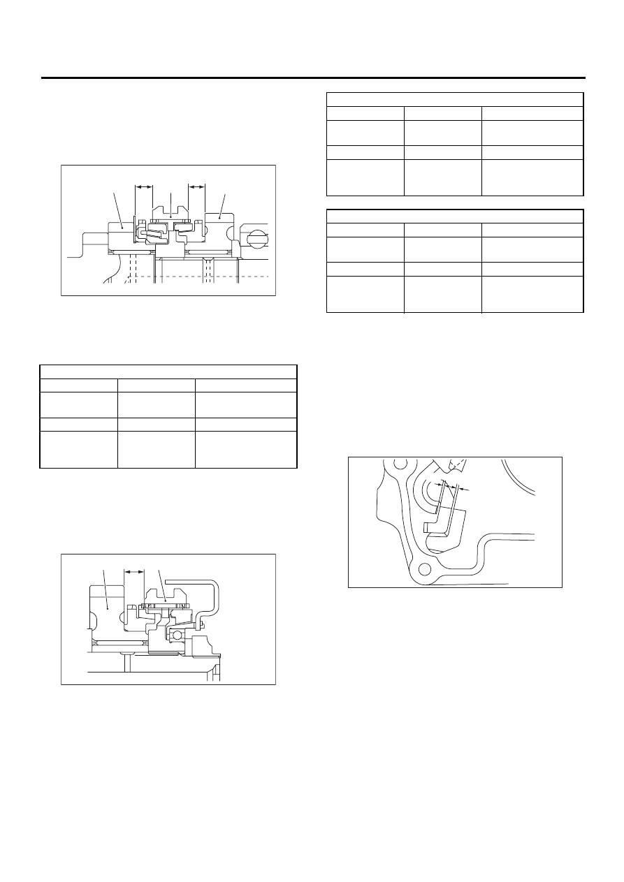
4) Inspect clearance between 3rd, 4th drive gear
and coupling sleeve. If any clearance is not within
specifications, replace shifter fork as required.

Clearance (a) and (b):

9.3 mm (0.366 in) 

5) Inspect clearance between 5th drive gear and
coupling sleeve. If any clearance is not within spec-
ifications, replace shifter fork as required. 

Clearance (a):

9.3 mm (0.366 in) 

6) Inspect rod end clearances (A) and (B). If any
clearance is not within specifications, replace rod
or fork as required.

Clearance (A): 

3rd — 4th to 5th:

0.5 — 1.3 mm (0.020 — 0.051 in) 

Clearance (B): 

1st — 2nd to 3rd — 4th:

0.4 — 1.4 mm (0.016 — 0.055 in) 

(A) 3rd drive gear

(B) Coupling sleeve

(C) 4th drive gear

3rd-4th shifter fork

Part No.

Mark

Remarks

32810AA061

1

Approach to 4th gear 
by 0.2 mm (0.008 in).

32810AA071

No mark

Standard

32810AA101

3

Become distant from 
3rd gear by 0.2 mm 
(0.008 in).

(A) 5th drive gear

(B) Coupling sleeve

MT-00314

( a )

( b )

( A )

( B )

( C )

MT-00315

( A )

( a )

( B )

5th shifter fork (Non-TURBO model)

Part No.

Mark

Remarks

32812AA201

7

Approach to 5th gear 
by 0.2 mm (0.008 in).

32812AA211

No mark

Standard

32812AA221

9

Become distant from 
5th gear by 0.2 mm 
(0.008 in).

5th shifter fork (TURBO model)

Part No.

Mark

Remarks

32812AA231

7

Approach to 5th gear 
by 0.2 mm (0.008 in).

32812AA241

No mark

Standard

32812AA251

9

Become distant from 
5th gear by 0.2 mm 
(0.008 in).

MT-00316

( A )

( B )

MT-109

MANUAL TRANSMISSION AND DIFFERENTIAL

COUNTER GEAR

23.Counter Gear

A: REMOVAL

1) Remove the manual transmission assembly
from the vehicle. <Ref. to MT-32, REMOVAL, Man-
ual Transmission Assembly.>
2) Remove the transfer case with extension case
assembly. <Ref. to MT-47, REMOVAL, Transfer
Case and Extension Case Assembly.>
3) Remove transmission case. <Ref. to MT-59, RE-
MOVAL, Transmission Case.>
4) Move counter gear shaft until it touches trans-
mission case, and remove snap ring with a suitable
tool.

5) Slide washer at rear of high-low counter shaft,
and remove straight pin from counter shaft.

6) Remove counter shaft from transmission case,
taking care not to drop counter gear and the two
washers.

NOTE:
• Be careful not to damage O-ring.
• Be careful not to drop straight pin on front side.

• Be careful not to drop two needle bearings and
collar contained in counter gear.

B: INSTALLATION

1) Install new O-ring and straight pin onto counter
gear shaft.
2) Install the following parts in main case (Right-
side), and push the shaft perfectly into case.
• Counter gear shaft
• Two counter gear washers
• Two needle bearings
• Counter gear collar
• Counter gear
• Straight pin
• Snap ring 
3) Install the transmission case. <Ref. to MT-61,
INSTALLATION, Transmission Case.>
4) Install the transfer case with extension case as-
sembly. <Ref. to MT-47, INSTALLATION, Transfer
Case and Extension Case Assembly.>
5) Install the manual transmission assembly on ve-
hicle. <Ref. to MT-35, INSTALLATION, Manual
Transmission Assembly.>

NOTE:
• Make sure that cut-out end surface of counter
gear shaft does not protrude above the end surface
of the case.
• Position the cut-out portion of counter gear shaft
as shown in the figure.

C: INSPECTION

1) After installing snap ring, measure clearance be-
tween snap ring and counter washer.

Clearance:

0.05 — 0.35 mm (0.0020 — 0.0138 in)

2) If the clearance is out of measured value, select
a snap ring and install to put clearance within mea-
sured value. <Ref. to MT-110, ADJUSTMENT,
Counter Gear.>

(A) Snap ring

(A) Straight pin

(B) Counter gear

MT-00317

( A )

MT-00318

( A )

( B )

(A) Counter shaft

(B) Counter gear

(C) Washers

MT-00319

( A )

( B )

( C )

MT-110

MANUAL TRANSMISSION AND DIFFERENTIAL

COUNTER GEAR

D: ADJUSTMENT

Selection of snap ring
If the measurement is not with in the specification,
select suitable snap ring.

Snap ring

Part No.

Thickness mm (in)

031319000

1.50 (0.0591)

805019010

1.72 (0.0677)

MT-111

MANUAL TRANSMISSION AND DIFFERENTIAL

GENERAL DIAGNOSTIC

24.General Diagnostic

A: INSPECTION

1. MANUAL TRANSMISSION

Symptom

Possible cause

Remedy

1. Gears are  difficult to intermesh. 
NOTE:
 The cause for difficulty in shifting gears
can be classified into two kinds: one is
malfunction of the gear shift  system and
the other is malfunction of the transmis-
sion. However, if  the operation is heavy
and engagement of the gears is difficult,
defective clutch disengagement may also
be responsible. Check whether  the clutch
is correctly functioning, before checking
the gear shift  system and transmission.

(a) Worn, damaged or burred chamfer of  
internal spline of sleeve and reverse 
driven gear

Replace.

(b) Worn, damaged or burred chamfer of 
spline of gears

Replace.

(c) Worn or scratched bushings

Replace.

(d) Incorrect contact between synchro-
nizer ring and gear cone or  wear 

Correct or replace.

2. Gear slips out.
• Gear slips out when coasting on rough 
road.
• Gear slips out during acceleration.

(a) Defective  pitching stopper or loose-
ness of installation bolt 

Tighten or replace.

(b) Loose engine  mounting bolts 

Tighten or replace.

(c) Worn fork shifter,  broken shifter fork 
rail spring

Replace.

(d) Worn or damaged  ball bearing

Replace.

(e) Excessive clearance between  splines 
of synchronizer hub and synchronizer 
sleeve

Replace.

(f) Worn tooth step of synchronizer hub 
(responsible for  slip-out of 3rd gear)

Replace.

(g) Worn 1st driven gear,  needle bearing 
and race

Replace.

(h) Worn 2nd driven gear,  needle bear-
ing and race

Replace.

(i) Worn 3rd drive gear and  bushing

Replace.

(j) Worn 4th drive gear and bushing

Replace.

(k) Worn reverse idler gear and bushing

Replace.

3. Unusual noise comes from transmis-
sion.
NOTE:
If an unusual noise is heard when the ve-
hicle is parked with its engine  idling and if
the noise ceases when the clutch is disen-
gaged, it may be  considered that the
noise comes from the transmission.

(a) Insufficient or improper lubrication 

Lubricate or  replace with specified oil.

(b) Worn or damaged gears and  bear-
ings 
NOTE:
If the trouble is only wear of the  tooth sur-
faces, merely a high roaring noise will oc-
cur at high speeds,  but if any part is
broken, rhythmical knocking sound will be
heard even  at low speeds.

Replace.


Content   ..  633  634  635  636   ..