Subaru Legacy III (2000-2003 year). Manual - part 633
MT-100
MANUAL TRANSMISSION AND DIFFERENTIAL
FRONT DIFFERENTIAL ASSEMBLY
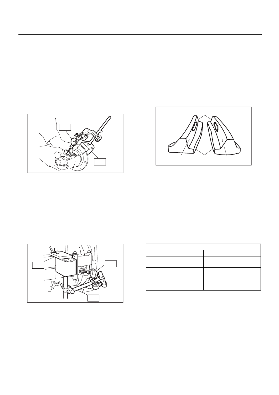
1. BEVEL PINION GEAR BACKLASH
Measure backlash between bevel gear and pinion.
If it is not within specifications, install a suitable
washer to adjust it.
NOTE:
Be sure the pinion gear tooth contacts adjacent
gear teeth during measurement.
ST1
498247001
MAGNET BASE
ST2
498247100
DIAL GAUGE
Standard backlash:
0.13 — 0.18 mm (0.0051 — 0.0071 in)
2. HYPOID GEAR BACKLASH
Set ST1, ST2 and ST3. Insert the needle through
transmission oil drain plug hole so that the needle
comes in contact with the tooth surface at a right
angle and check the backlash.
ST1
498247001
MAGNET BASE
ST2
498247100
DIAL GAUGE
ST3
498255400
PLATE
Backlash:
0.13 — 0.18 mm (0.0051 — 0.0071 in)
NOTE:
If backlash is outside specified range, adjust it by
turning holder in right side case.
3. TOOTH CONTACT OF HYPOID GEAR
Check tooth contact of hypoid gear as follows: Ap-
ply a uniform thin coat of red lead on both tooth sur-
faces of 3 or 4 teeth of the hypoid gear. Move the
hypoid gear back and forth by turning the transmis-
sion main shaft until a definite contact pattern is de-
veloped on hypoid gear, and judge whether face
contact is correct. If it is inaccurate, make adjust-
ment. <Ref. to MT-100, ADJUSTMENT, Front Dif-
ferential Assembly.>
• Tooth contact is correct.
F: ADJUSTMENT
1. BEVEL PINION GEAR BACKLASH
1) Disassemble the front differential. <Ref. to MT-
95, REMOVAL, Front Differential Assembly.>
2) Select a different washer from the table and in-
stall.
3) Adjust until the specified value is obtained.
Standard backlash:
0.13 — 0.18 mm (0.0051 — 0.0071 in)
MT-00285
ST1
ST2
MT-00293
ST3
ST2
ST1
(A) Toe
(B) Coast side
(C) Heel
(D) Drive side
Washer
Part No.
Thickness mm (in)
803038021
0.925 — 0.950
(0.0364 — 0.0374)
803038022
0.975 — 1.000
(0.0384 — 0.0394)
803038023
1.025 — 1.050
(0.0404 — 0.0413)
MT-00294
( B )
( A )
( C )
( D )