Subaru Legacy III (2000-2003 year). Manual - part 570
AT-14
AUTOMATIC TRANSMISSION (DIAGNOSTICS)
TRANSMISSION CONTROL MODULE (TCM) I/O SIGNAL
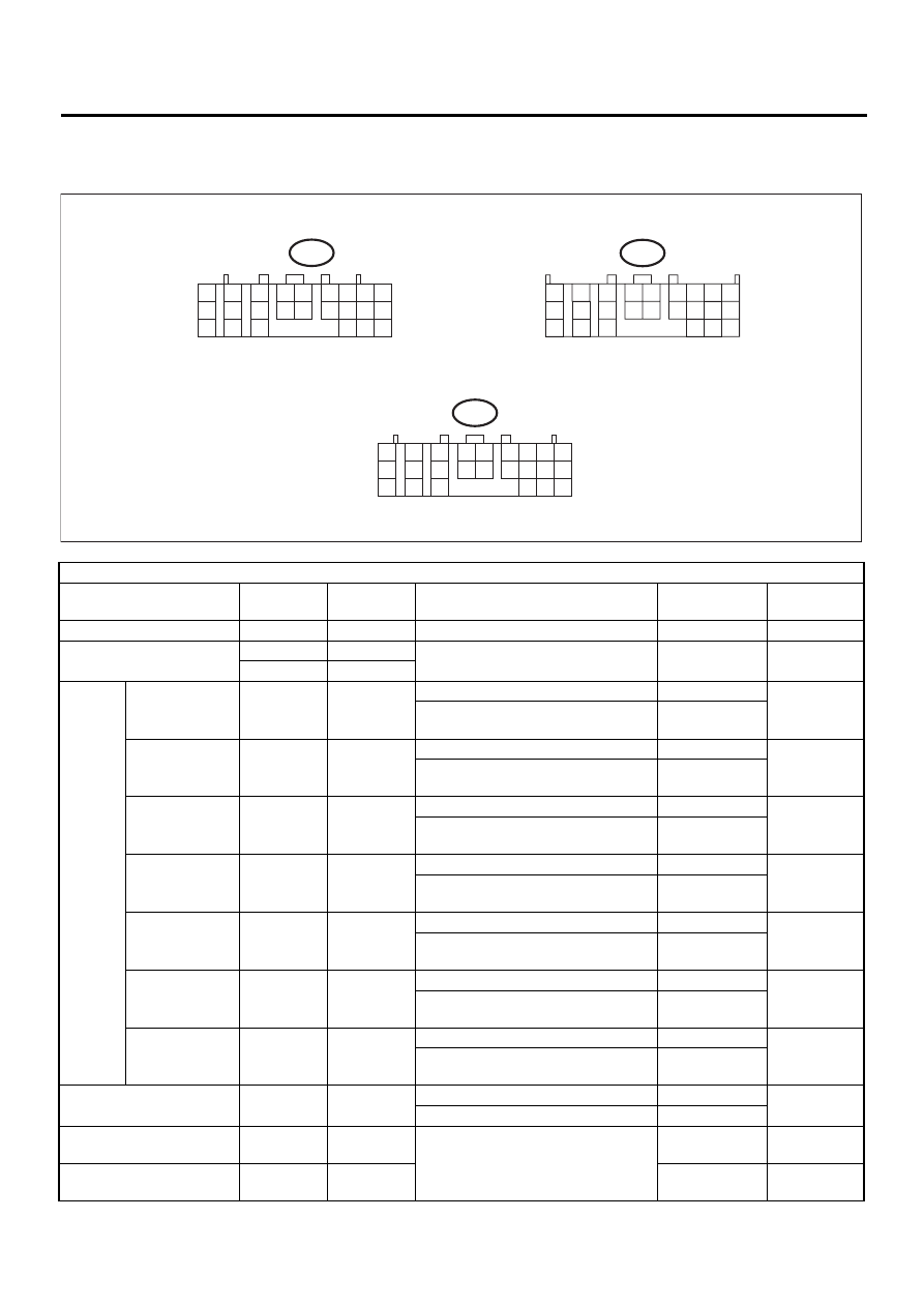
5. Transmission Control Module (TCM) I/O Signal
A: ELECTRICAL SPECIFICATION
Check with ignition switch ON.
Content
Connector
No.
Terminal
No.
Measuring conditions
Voltage (V)
Resistance to
body (ohms)
Back-up power supply
B56
1
Ignition switch OFF
10 — 13
—
Ignition power supply
B54
23
Ignition switch ON (with engine OFF)
10 — 13
—
B54
24
Inhibitor
switch
“P” range switch
B55
1
Select lever in “P” range
Less than 1
—
Select lever in any other than “P”
range (except “N” range)
More than 8
“N” range switch
B55
14
Select lever in “N” range
Less than 1
—
Select lever in any other than “N”
range (except “P” range)
More than 8
“R” range switch
B55
3
Select lever in “R” range
Less than 1
—
Select lever in any other than “R”
range
More than 8
“D” range switch
B55
4
Select lever in “D” range
Less than 1
—
Select lever in any other than “D”
range
More than 8
“3” range switch
B55
5
Select lever in “3” range
Less than 1
—
Select lever in any other than “3”
range
More than 8
“2” range switch
B55
6
Select lever in “2” range
Less than 1
—
Select lever in any other than “2”
range
More than 8
“1” range switch
B55
7
Select lever in “1” range
Less than 1
—
Select lever in any other than “1”
range
More than 8
Brake switch
B55
12
Brake pedal depressed.
More than 10.5
—
Brake pedal released.
Less than 1
VDC communication signal
+
B56
9
Ignition ON
(+) — (–)
Pulse signal
—
VDC communication signal
–
B56
18
(+) — (–)
Pulse signal
—
AT-00642
to
B54
1
2
7
8
9
5
6
3
4
10
11
12
19
20
21
13
14
15
16
17
18
22
23
24
to
B55
1
2
3
4
10
11
12
19
20
21
13
5
6
14
15
7
8
9
16
17
18
22
23
24
to
B56
1
2
7
8
9
5
6
3
4
10
11
12
19
20
21
13
14
15
16
17
18
22
23
24