Subaru Legacy III (2000-2003 year). Manual - part 167
EN(H4SO)-280
ENGINE (DIAGNOSTICS)
DIAGNOSTIC PROCEDURE WITH DIAGNOSTIC TROUBLE CODE (DTC)
CC:DTC P1498 — EGR SOLENOID VALVE SIGNAL #4 CIRCUIT MALFUNCTION
(LOW INPUT) —
• DTC DETECTING CONDITION:
• Immediately at fault recognition
• TROUBLE SYMPTOM:
• Erroneous idling
• Engine stalls.
• Engine breathing
CAUTION:
After repair or replacement of faulty parts, conduct Clear Memory Mode<Ref. to EN(H4SO)-47, OPER-
ATION, Clear Memory Mode.> and Inspection Mode <Ref. to EN(H4SO)-40, OPERATION, Inspection
Mode.> .
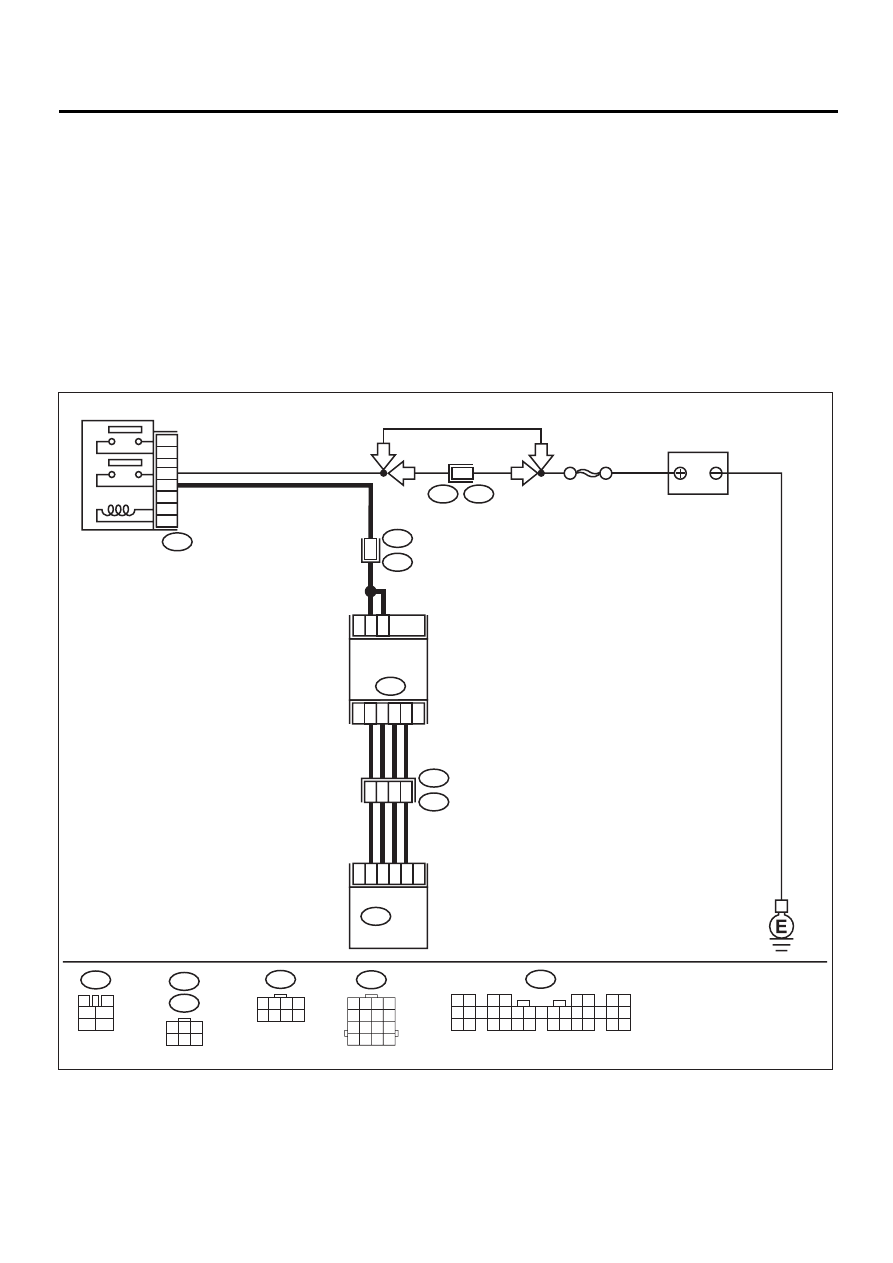
• WIRING DIAGRAM:
EN-01129
F44
B61
6
RHD
RHD
BATTERY
SBF-5
B47
MAIN RELAY
1
2
3
5
4
6
F44
1 2 3 4
5 6 7 8
1
6
3
4
1
B22
E3
E58
B328
EGR
SOLENOID
VALVE
2
5
E18
5
6
4
3
ECM
18
17
16
15
B134
B22
1 2 3 4
5 6 7 8
9 10 11 12
13 14 15 16
B47
3
4
5
6
1
2
LHD
LHD
E18
B328
1
3
4 5 6
2
B134
1 2
3 4
5 6
7 8
9 10 11 12 13 14 15 16 17 18 19 20 21 22 23
24 25
26 27 28 29
30 31 32 33
34 35